CNC Spindle Rotation
Here's a discussion of router spindle control and the reasons to use "conventional" or "climb" cutting paths. January 19, 2012
Question
I�m curious of a few things about CNC machines when cutting plywood, PB, melamine, laminate, etc. Does a fixed router on a CNC spin only clockwise under power or are there machines with a reversible motor allowing it to spin counterclockwise.
With that being said is there a specific routing orientation that would be used. Like when using a hand held router I would move it counterclockwise around a work piece if I was working on the edge. How does this apply to CNC cutter movements when not edge treating?
When cutting nested based parts does the router move in a clockwise or counterclockwise fashion consistently or is it just based on the most optimized path. I am aware of ramping the cutter in gradually and over lapping the cut to gain a clean face on each side. But what are some others?
Forum Responses
(CNC Forum)
From contributor D:
All spindles spin clockwise, some counter clockwise as well. You determine which way to cut out a part, not the machine, so whichever way around it you want to go.
From contributor B:
Spindles can spin both CW and CCW. M3 is CW, M4 CCW and M5 Off. It is a function of the frequency inverter but you need to have LH thread tool holders so the collet nuts do not loosen when running CCW.
From contributor A:
In terms of spindle rotation: On most CNC machines, spindles can rotate in both directions by selecting the rotation in the program or in the tool data. It's very rare to find a spindle on a machine that does not spin in both directions. An example of this in use is when a board is edge-banded and then sent to a router for shape cutting, a left handed router bit may be used to prevent the edge-banding from being torn off.
In terms of cutting direction: The majority of work in man-made materials such as particle board and MDF etc is done in conventional cutting direction.
However, when dealing with solid wood where tear-out can occur on cross grains, climb cutting is used. Another use of climb cutting is when doing a finish pass in materials such as acrylic, aluminum, steel etc.
From contributor Z:
The question about spindle rotation is rather straight forward; it�s either clockwise or counter clockwise. The programmer selects the direction of rotation at the time he defines the tool. Every tool is designed for one or the other rotation, not both. It�s fairly common to have a tool made in pairs one CW and one CCW when cutting solid wood and use them both to prevent tear out.
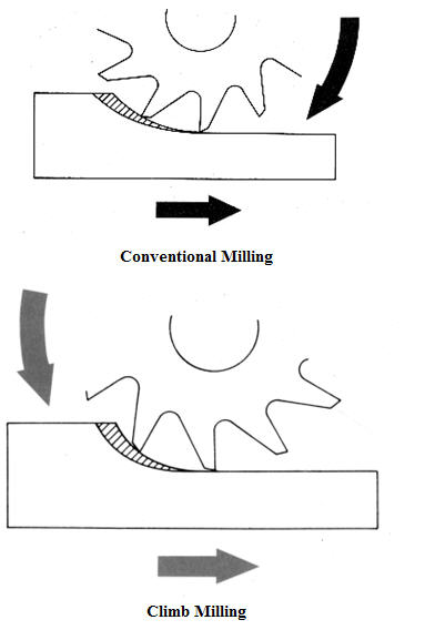
The two ways to cut are commonly referred to as �climb� and �conventional .� Hand feed machines are almost always conventional cut because climb cutting has a tendency to pull the material out of the operators grip. See the picture below. Conventional cutting starts at the narrow part of the chip, or the tangency point. Climb cutting starts at the widest part of the chip.
Most all programming systems (CAM) give the programmer the choice to climb of conventional cut. It�s most common to cut using a climb cut on the man-made materials you mentioned. But there are circumstances that can change the cut direction.
Click here for higher quality, full size image
From contributor H:
I do believe you inadvertently reversed the identification labels on your two climb/conventional cutting diagrams.
From contributor Z:
Onsrud Cutter is a large router bit manufacturer and a well know supplier to thousands of woodworking companies. They have done considerable research into router bit design. I consider them to be an excellent resource for accurate information. For your reference, below is a copy of a picture from the "Onsrud Cutter CNC Production Routing Guide" page 15. It is the same as my picture in my last post. I believe the information is correct.
From contributor W:
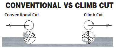
I have always thought of climb cutting as the cutting edge entering the material and slicing as the edge enters the material (router wanting to pull you into material) and conventional in the opposite direction, as shown in the second diagram posted.
From contributor Z:
It is a matter of perspective. The first picture shows a moving table machine where the work piece moves. The shaded area shows the chip. Note that the material has been cut away behind the cutter. The bottom arrow shows the movement of the work. The second picture shows the tool moving.
From contributor M:
Could it be that the bits are different in the picture? To me one is a right hand and the other is a left hand rotation. What the OP was asking is about clockwise and counter clockwise (climb and conventional cutting). Someone has mentioned that it is controlled by the programmer. Each CAD/CAM package will have this setting in the tool-path area but you need to know when to use it. It is depending upon what material you are using. Certain plywood and lumber may use "climb" and MDF/Melamine may use conventional and sometimes you can use both.
I have heard of some CNC users that don't have an ATC using a first pass as rough cut and then reverse direction (not rotation) to clean up the edge. Or an interior cut will be the opposite of an exterior cut. Most software already recognizes the difference and you will see this with different color vectors.
There are many strategies to use but it will come with experience and knowing what tooling gives the best results with each material and the tool-path strategy in your software.