Question
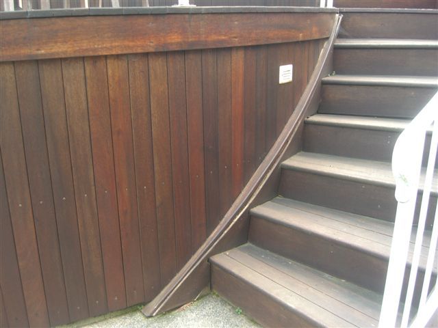
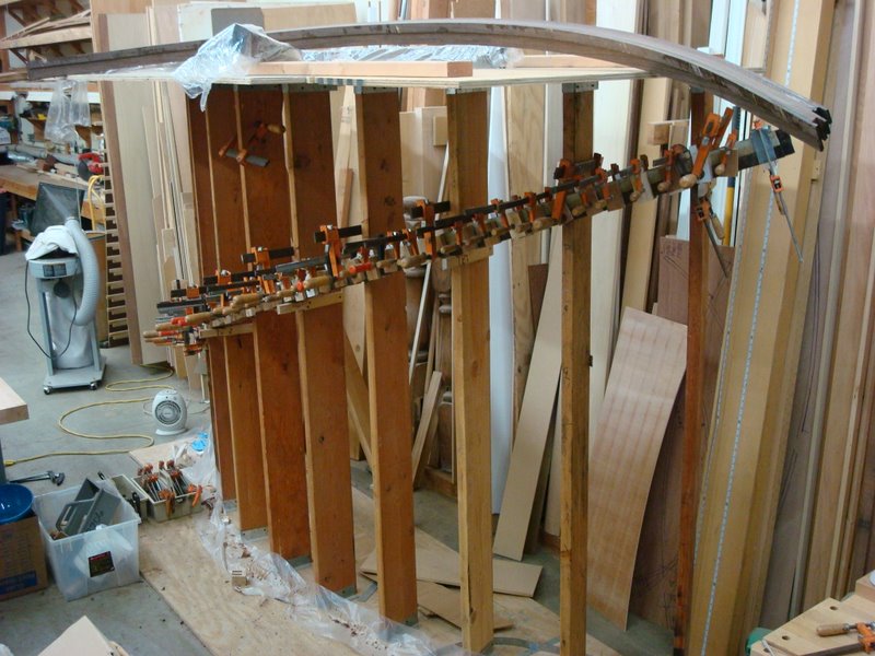
We are building wine racks similar to the picture below that are under a curved staircase along a radiused wall. We have the racks built to the radius no problem but I have a few questions on the 1 x 2 "crown" that travels on the curved wall up the slope of the stair on the top of the racks.
I have searched the archives and wasn't able to find a straight forward answer. Maybe there isn't one? I can figure the helical radius and have actually made a radiused piece that we can use but it requires some clamping to hold the twist required. Is there any way to figure the twist required to keep the trim oriented vertically as it goes up the cabinet?
I am laminating it up on a curved form flat on the table. It's not worth building a duplicate wall in the shop to glue up such a small trim to the proper twist. What we have will work but I am just wondering if there is a way to calculate the twist? In my mind I picture a curved clamping form with wedges of specific angles every 6" or so to get the right twist - or at least close. Are there any math majors or stair gurus out there?

Forum Responses
(Architectural Woodworking Forum)
From contributor J:
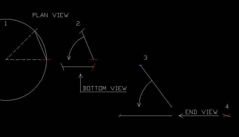
I would model this in CAD.
Step 1
Draw a circle that is the radius that you are working with.
Draw a line so that its midpoint is on a quad of that circle.
Draw another line on the circle that is at the desired degree of turn.
Step 2
Rotate these three lines so that the third line is horizontal.
Step 3
Change your view so that you are looking up from the bottom of the screen.
Rotate the three lines so that the third line is horizontal.
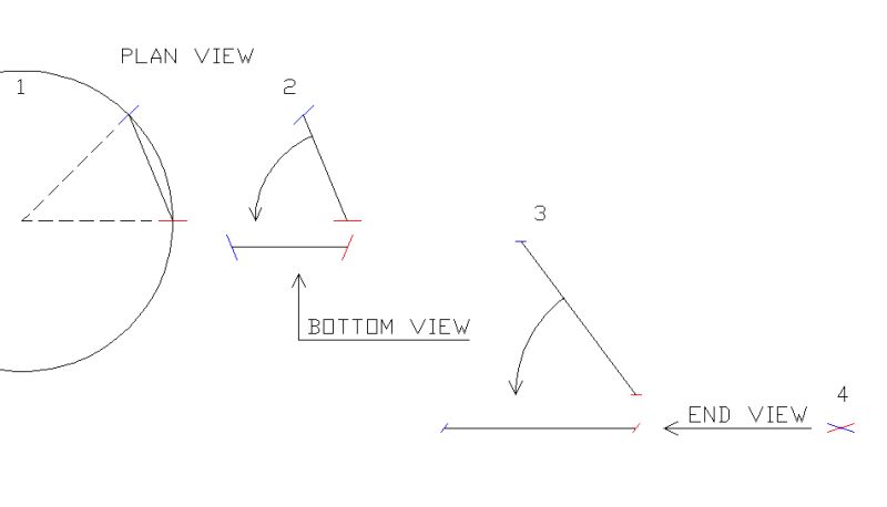
Step 4
Change your view so that you are looking from the right side of the screen.
You can now see, and dimension, the angle between the first and second line.
Go to the job site and determine the rise and run of the stairs and then transfer those dimensions onto your curved form. Then clamp the laminations to the form. Just visualize this in the vertical orientation (as if you had built the curved wall) and then rotate it flat to the table.
We've done this without building a full vertical stud wall as well. We made several horizontal ribs from MDF that matched the wall radius and then faced them with bending plywood. To keep it simple we clamped the form to a vertical post so it could be upright just like the wall. This made for quick form setup and an accurate run/rise for the moulding clamp-up. No twist calculations had to be done as the moulding was pressed against the wall form.
A lot of folks will suggest making a part of a given radius, then tilting it up into place. This will not have the twist, as it sounds you have already found out. If the radiused part is wider and thicker than its final dimensions, then you can force the vertical and horizontal faces onto the part with careful layout, bandsawing, spokeshaving and surfacing. Once complete, you will agree that the twisted lamination on a form would have been faster and gives a better part. Your form will need to have the radius in plan, and the rise/run angle plotted along its length. There is more than one way to do this, as suggested - you don't need full height or full length in most cases. As for modeling in CAD, once you have it all drawn in CAD, then what do you do? You still have to make the part - any good shop hand that has some curve experience can visually grasp what has to be done.
I almost never build any bending forms though or re-saw and bend or twist wood. I don't need a five axis CNC or Compass Software either (I do think CAD would be nice). While searching for short-cuts, I have come up with a simple helical curve formula and even the twist (torsion) calculations but all of this is no real advantage over a single drawing. You can read all about this in any old stair book and you might find it interesting if nothing more.
After looking up orthogonal projection, I think this is probably the closest method to what I was thinking. How did you go about doing it? I understand the helix calculation but I am interested in the torsion calculation if you don't mind sharing.
Do you guys have any suggested books on the topic? I saw in the archives a couple references to DiChristinas book and also a book by Mowat. I might be getting in a little over my head but now I'm mentally invested.
To illustrate the twist, if you were to laminate a 1x4 half circle with the 4" being oriented vertically, similar to a piece of base on a curved wall. Now elevate one end of the half circle say 20 degrees for under a stairs. The two ends are no longer vertical. They would both need to be twisted to be plumb with the wall. The twist needs to continue along the entire length so it remains plumb and tight to the wall.
I hope I'm not confusing anyone else. It can be a mind bender if you haven't tried it but it's easy to see if you try a piece. Yes, if you made the block wide enough to accommodate the twist you could use a spokeshave to create the twist which I think is similar to what was referred to earlier.
However, if we have the three dimensions, we can define the part. The twist comes in automatically as the strips (let�s say 1/8" x 1-7/8" - 6 pieces) are laid in place. The one thing to remember is that at any point in the part, a section square through will reveal a rectangle with four 90 degree corners, as long as the section is in the same plane as the centerpoint. Most people will let the strips slip and define a parallelogram without square corners. The twist is automatic, so to speak. The best part is that no math is required.
When I apprenticed in a shop way back when, the shop built curved stairs all the time. I would watch from a distance, convinced that higher geometry, calculus, and trig were necessary to get then up in the air. Once I started building the stairs, I learned that it was as easy as two layout sticks, and the math was no more complex than anything else I had built. Like all great skills, the trick (if there is one) is in the method and knowledge the craftsmen have. The helix comes up naturally, and the grace comes from the unity of simple curves.

I need to build in a small amount of twist into a 5' long 3/4" x 1 1/2" piece of trim with a radius of approx 9' and a 20 degree rise. So I guess I just want to know how much twist, (torsion) as pointed out, was needed to be able to modify a simple single radius bending form? Or if it was even possible?
Contributor H - Thanks for pondering it. I already had a bending form for the baseboard that I only needed to modify a bit to change the radius for the helical section. My form wasn�t tall enough to allow me to include the rise in the glue up. It was more like the "L" brackets used to glue up a handrail. I was just hoping by adding some angled wedges to the new form I could avoid making another taller curved form?
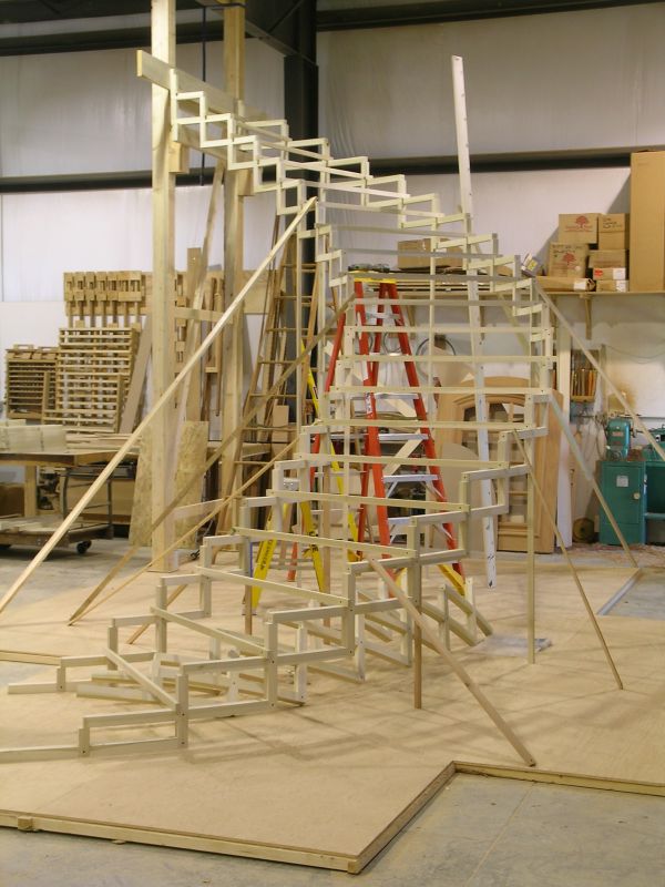
Contributor O - were the stringers in those photos laminated up on a full sized wall form? They look hollow in the center like the tread/riser supports pass between two skins? If so I'm assuming the tread supports are cut or laminated to correct radius?
To figure twist bevels for regular helix curve, based upon a tangent plane intersection angle:
90-(txa)/2=b
t= twist factor constant*
a= angle of the floor plan curve in degrees
b= plumb bevel angle applied to the plank at both joint ends.
*Twist Factor (like Cord Factors) are a calculated value and must be determined for each degree of pitch (and yes, I am making this stuff up). I've also determined the formula for this but it's rather cumbersome. I am still trying to reduce it. You can ask me for a TF if you want and I'll figure it up.
Anyway this seems to agree with the geometric layout. When I am through calculating Twist Factors (for each degree of pitch) I'll put them all on a chart and be able to use them to verify the drawing (or possibly omit the drawing altogether)?
I didn't get any of this from Newton or Leibniz and I am still trying to understand the Euhler, Frenet-Serret formulas. Their helical curve computations are about a dozen more entries then you need but their "osculating circle" concept was the key.
Example: According to my mixed-up math, a 30 degree pitch angle has a TF of .49865.
Let the floor plan angle be 70 degrees...
.49865 x 70 divided by 2 = (STO) 90 - (RCL) = 72.54
The CAD thing though looks like the way to go to me but I haven't jumped through that hoop yet. The books you've mentioned are all good and the knowledge of these methods will be invaluable when the helical curves turn out to be anything but regular or simple. You can forget the math then because you'll be back to the drawing board.
Orthogonal Projection has nothing to do with any of this but is the predecessor of the tangent methods of the 1850's. It still works though and is the easiest to understand. This was the first systematic approach to the art of helical woodwork and a giant leap for stair builders.
"From contributor Z�:
The original question is about twist math. I figure the twist by first drawing the handrail (using Vectorworks 2-D CAD) as if it were unrolled. Really what I do is draw both the inside and the outside of the handrail. The inside and outside of the handrail both begin at the same height and end at the same height. The difference is in the length they traverse between those two points. The outside of the handrail will travel farther than the inside of the rail. If you carefully draw these two lines you will see that the rate of rise (rise over run) is different. I typically draw these two and then let them intersect at their mid points. This yields a drawing that looks like a relaxed X. If you were to measure between the end points of the two lines, that would be your twist.
Math being tricky for myself, I had a hard time understanding why the rail had a twist at all. What helped me figure it out was to look at a circular stairway - the steps themselves. The steps or stairs are shaped just like the handrail, only at a bigger scale. For example, if a circular stairway had a well side rise of 7 inches and a run of 7 inches, the well side "pitch" would be 45 degrees or 7/7. On the "anti-well" side, that very same stairway would have the same rise of 7 inches, but could easily have a 30" run. So the pitch would be 7/30 or 13.13 degrees. If you were to draw those two pitches like I described above, you would see that the stairway is itself twisted. "
Contributor W - any chance you were one of the posters? I am interested in how you calculate your twist factor constant but I can understand if you don't want to go into it. I would like to try using it for 20 degrees if you don't mind figuring it up or telling us how.
I did order DiChristinas book now that this question has taken over my free time. Yes I do still realize that I could avoid these steps by just building a curved form but now I'm on a mission.
Helical Handrail Math for Spiral Stairs
I actually start by calculating the bevel angle for a ninety degree floor plan helix using tangent layout methods as described in the book. Instead of drawing it all out though, I've just calculated the angle. After having determined the total twist through 90 degrees, I then re-figured for the amount of twist for each degree. This is the number that I am calling the "Twist Factor."
I don't think these figures have any connection to "torsion of curves" or Differential Geometry (which I couldn't decipher anyway). My methods are just tangent calculations that are made to fit the helical handrail scenario. I actually came up with this quite a few years ago but I didn't have a reliable helix curvature solution then.
The whole math thing though only works for regular helix computation. The minute there's a change in pitch within the plan radius, I am back again in the 1850's (not such a bad place though, those guys were pretty good). I am quite sure the CNC guys today would have a good laugh over all this but I suppose someone had to think things through and write their programs?
Yep, I have participated in several related exchanges here and really appreciate the opportunity to hear from some gifted and practical people. I think I was the original poster for the one you're asking about. I believe I was looking for some other ideas or perhaps some validation.
I think the combined helical lines of a curved staircase represent some of the most beautiful and fascinating architectural art forms. It can be an interesting and even addicting life's work if you let it.
Most of our stairs are tied to a wall at the outside skirt, but are left open underneath. Again, there is no math other than layout from a center point and dividing the vertical height and the run of each tread.
I also think it's interesting that there really isn't a standardized (or approved) method for the construction of self-supporting curved stairs. No wonder we often have difficulties getting them approved by local building departments. Every stair guy or company I know (including me) builds them a little (or a whole lot) different and each of us thinks we've got it all figured out. You're right about the math though, the less I use it the better off I am, but it is fun to push the little calculator buttons.
Contributor J, do you ever actually have to touch the wood? You guys scare me. I love to work the wood (at least a little) with my hands and you CNC gods are taking that away. Good for you really (and probably bad for me). This is all a very twisted topic but a bit more interesting than building square cup and saucer boxes don't you think?
The manager always told me that he wanted to be able to shove wood in one end, push a button, and a stair would come out the other end. I always told him that was a dangerous way to think. I believe that if you over automate sooner or later something will happen, an oddball situation or some technical failure, where you would push the button and nothing would happen and the people that knew how to do things manually would have forgotten how or are gone.
Anyway, back to the topic, I think that this is great to discuss how to solve something just for the sheer fun of it. There needs to be more of that. I am going to have to study these formulas in more detail. It�s very interesting. I can handle algebra and trig ok, but I can no longer do simple math without a calculator. There�s that over automation problem again.
The photo above is a bit misleading since that stair was made differently. We normally spend a half day in layout, then a half day S4Sing the blocks, then bandsawing the curves and the notches. These are all assembled (glued, screwed and clamped) to the risers in what looks like a jumble. Then, in a matter of an hour, the whole stair goes up one rise at a time, with props to support it along the way to the header.
Put a few clamps on it to hold it in place and then draw a vacuum in the bag. The only math involved would be measuring down one foot at each style. You should have done this before installing, so the trim to run wild before installing up to end-walls. Life is hard enough. You have to keep it simple whenever you can.
Contributor K - normally that would work but in this case the trim is actually what holds the vertical legs at the proper distance apart and at the proper radius. We need to make the trim first in order to assemble the cabinets. We already had forms for the horizontal trim so it just got me thinking there should be a way to do what we needed with just some modifications to it. I think beyond that it just turned into an interesting topic to do some light reading and learn something new.
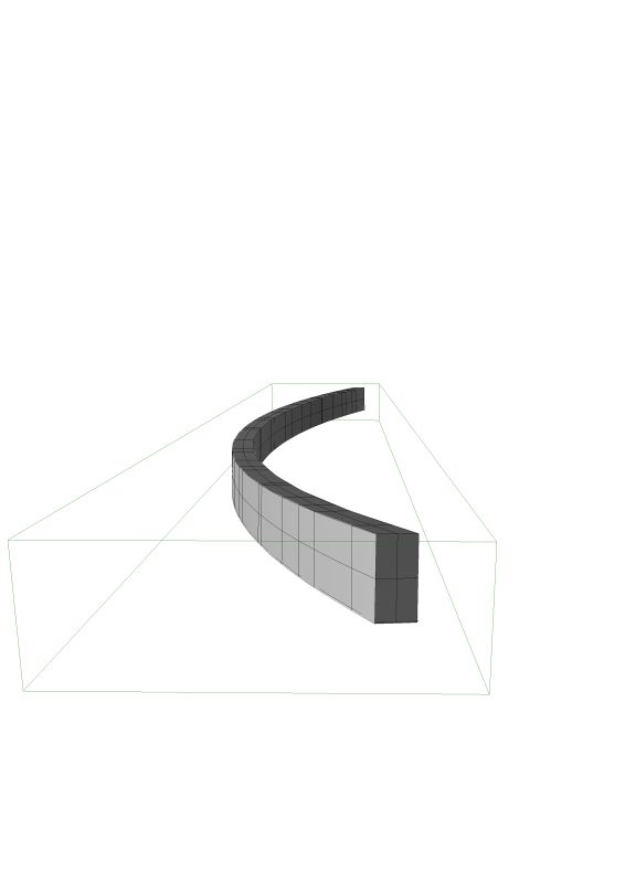
I got to thinking about your question and I would like to put a thought out there. How about we model in 3-D your exact situation? You provide a few critical measurements and the profile of your crown and I will step by step draw it in 3-D. In the process I think we will all be able to see what it is that you are building, we will be able to see the power of a 3-D model and with any luck we can all learn something. You see I completely agree with you and with some of the other posters when they shy away from the math involved in fabricating a helical piece. We should only use math if it moves us forward in the production of the piece. For me and I think for a lot of people a visual guide is easier to use. In my experience a good drawing is well worth the effort.
However, continuing anyway, I think that if you run your laminations along a narrow wall radius form, in effect parallel to the floor, and figure out the required twist, you still have a problem once the blank is glued up. The run along the floor, that is the plan view run, is shorter than the actual run up the curved wall. While you may think that this can be covered by just making two pieces, or by the form being long enough to accommodate the needed length, there is more to it than that. With the wall and form radius at 101 3/8" your glued up blank will be the same.
However, since the needed piece of moulding is helical, that 101 3/8" radius blank won't lay flat on the wall when tilted to climb with the ceiling. This is because the radius becomes larger as you climb the wall.
On the plan view you have a given chord length and rise that determines the radius. When you translate that up the curving wall, the rise of the arc (the rise is actually parallel to the floor) remains the same, but the chord length is going to increase since the piece of moulding needs to be longer then the chord length in plan view. That means the radius has to change, in effect becoming larger.
Since you glued up your blank on a 101 3/8" radius form, and the actual needed radius is larger, the moulding is going to hit the walls at both ends but not in the middle. Now with the size of your S4S profile you may be able to overcome this by pushing it into place. This conversation though has been more about mathematical theory than actual fit.
Helical radius= 114.80"
Helical arc length= 67.30"
Bevel angles= 83.89 degrees
This (center-line) information is all I normally require to cut and square a piece from a solid arc. I can usually do this in about the same time (or less) than it takes to build a bending form, re-saw the stock and laminate it. These numbers are all about actual fit and the 3-D modeling (I believe) is all about getting the machine to do the work for you, which should be better still. For me, this is also about learning something new (which is why I am here).
1. You have not given me enough information to answer your question.
2. You are not describing a helix. You are describing an ellipse.
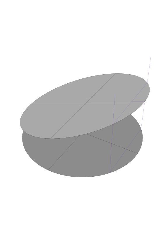
We need to be very precise about our language. Especially when we are thinking about these compound curves. A helix is a circular ramp. The simplest helix being like a screw thread and having a constant pitch. If you can picture 360 degrees of turn on that helix you can see that the beginning point and the ending point are vertical to each other. The points on the helix do not lie in a plane. An ellipse on the other hand is a tube bisected by a plane. This is what you are asking about � there are a couple of drawings below.
I can hear the keyboards whirring into action but never the less this is correct. Now you have not given us enough or correct information because you have not indicated where your bookcase intersects the ceiling plane. It is possible that your beginning point and your ending point are the same distance from the floor. This will give you one solution. If on the other hand you beginning point is at the lowest point on the ellipse and your ending point is at the highest point of the ellipse we would have a different solution.
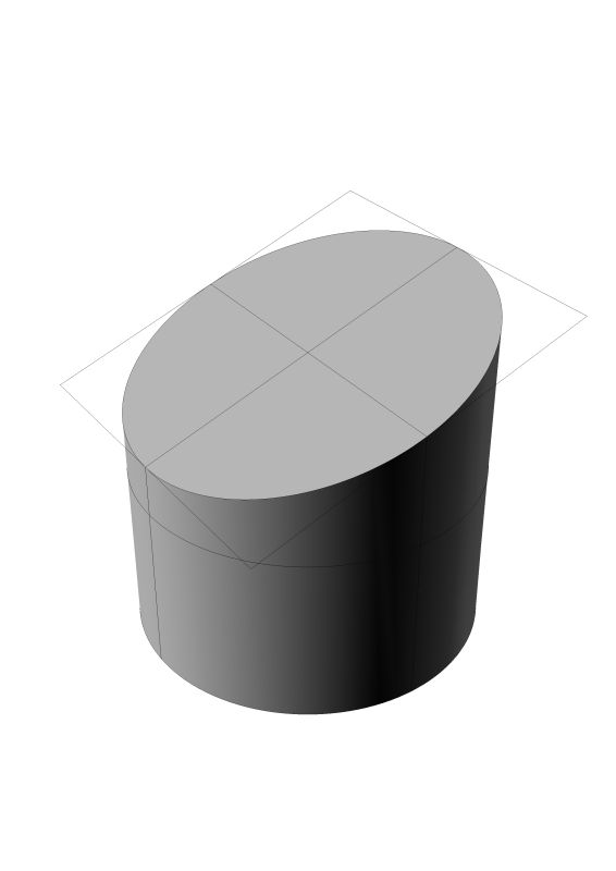
Here are a couple of drawings of a helix.


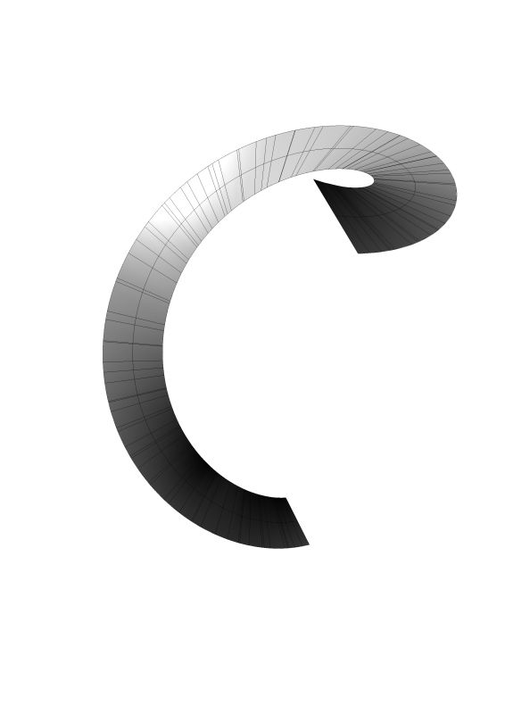
You can see the difference in the shape when you look from a plan view. More correctly, when you look from a perpendicular point of view to the elliptical surface. There is no perpendicular to a helix.

Here is the perpendicular view of the ellipse.
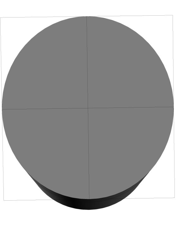
How is the questioner describing an ellipse? In order to define an ellipse we need major and minor axis. I understand your plane view cylinder bisection, but how did he specify that with his X Y Z coordinates? To be absolute with our language, there is only one definition of a helix. Anything other than a straight line wrapping regularly around a cylinder is not a helix.
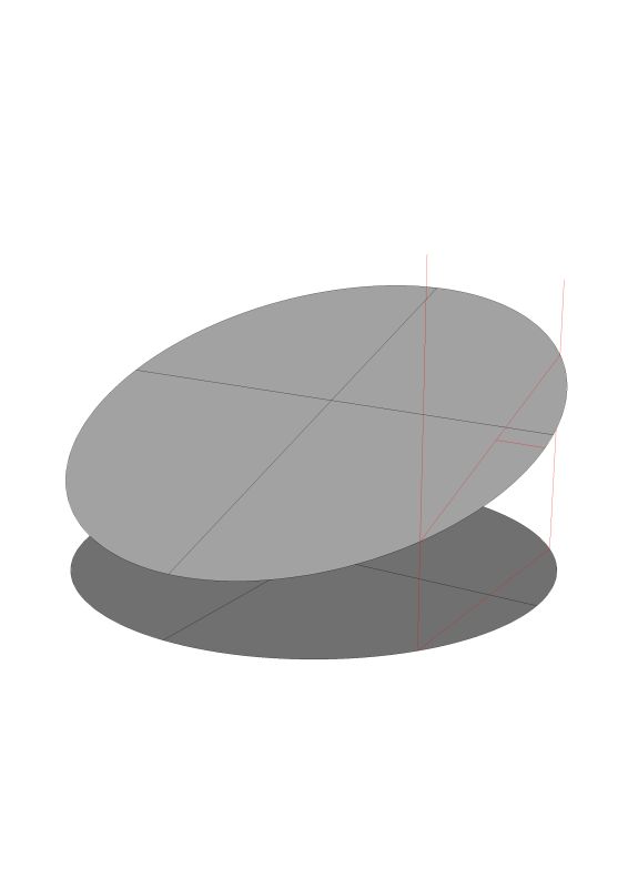
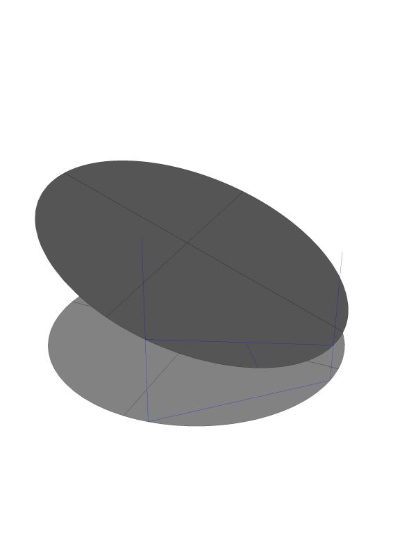
In all of these version I used the same dimensions, I simple placed the bookcase in a different place along the ground circle. Where the top of the bookcase intersects the ceiling is a different shape for each one of these versions. In version one the height of the elliptical section is 19.732" in version two it is 20.760 and in version three it is 20.344. It all depends on how his book case is placed in relationship to the ceiling.
Here is version one.
Here is another option - call it version two.
Here is yet another possible version. You see without knowing the height above the floor that his bookcase intersects the ceiling we cannot know a solution.
If you were to draw on paper a base line of 63.25 long (to scale), and a line from one end (start point) of the base line rising at 20 degrees that will meet (end point) a line perpendicular from the end of the floor/plan line, then you have a 2-D model of the original problem and a right triangle. Bend your paper to the correct plan radius 101.375 (scale), and you now have a 3-D version of the part's place in space. If you mentally continue the rising line you see the radius stays the same, and a helix is formed.
In regards to the earlier posts the dimensions given are adequate; two angles (20 and 90 degrees) and base line (63.25) will yield a simple right triangle. The start and end point elevations are given/produced with no guesswork. The part will have twist and the amount of twist will be constant through the length of the part. I don't know the higher math methods to explain it, but the simple math works well. In all the stairs, it has never been wrong.
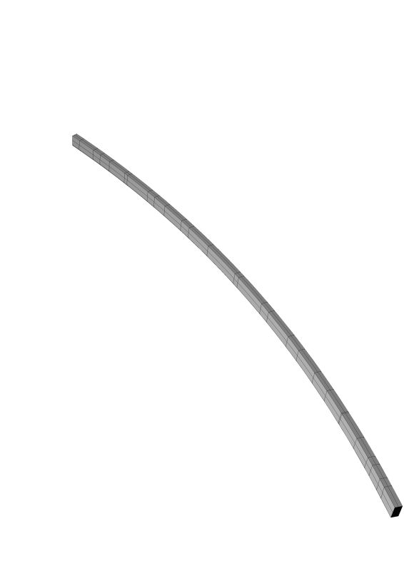
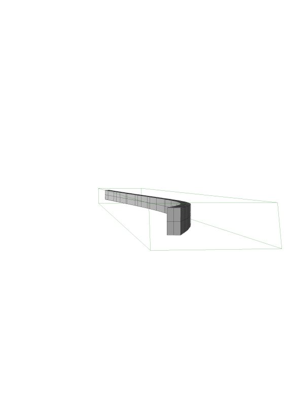
More views.
Here is the solution for the twist of the bottom of the helix. It is not much of a twist. I used the method you quoted in your earlier post.

Your drawing will need to do all of that in order to be useful to someone (like me) who doesn't own a CNC. I am also interested to see if my math matches your software solutions. I think part of the translation problem is that I am always working first from a single center line of the helix while the CNC mindset is working with the total helicoidal surfaces. For precise language I believe a circular ramp is called a helicoid and not really a helix.
When you are asking about the twist my solution shows the twist with the middle of the pieces crossing, or the middle being level and the ends both twisting from there. The amount was .08". That would be .08" on both ends. If you were to make the lower end, for example, start in the same plane then the other end would have .16" twist. One of the reasons that I believe the CNC method is revolutionary is that you do not need to do any of that figuring. Once I have modeled the piece correctly the router can cut it. It�s really a quick process.
I think your drawing earlier answers my question on whether or not this could be made on a flat radiused form. I may be wrong but it doesn't look like any of the 3/4" edge lies in the same plane. If that's the case it eliminates the flat form idea. It was probably a bit confusing to me since the curves and twists were so minor. If they had been greater it would have exaggerated the twist and been much more obvious. Lucky for me the trim was flexible enough to be coaxed into place.
Yes every helical component of a curved stair used to be laid-out and cut from solid timbers, including the handrail, curved stringers, moldings and even the twisted soffit framing members.
The idea of ripping up a perfectly sound piece of wood into bendable strips was completely ludicrous (especially if you had to do it all by hand). Working strictly with hide glue and homemade wooden clamps must also have been a limiting factor.
Today, CNC technology is just beginning to reintroduce some solid wood construction into the craft. I believe Contributor A is probably a rare example of this new (and old) approach.
The next woodworking leap will probably come from robotics. After that we can all take our tools and hang them on the wall.
Let's see, it would take me about an hour to lay it out, another two to build the jig, cut and plane the pieces and trial bend. There would also be time to mix the glue, clamp the oozing serpent to the form and a day's work is done. Next morning, off it comes, scrape and sand all that nasty excess glue off.
Now, either I have a nice twisted square shape, or i have the finished part in my hand depending on whether or not I decided to pre-mill the profile. If I have a twisted square in my hand, I still have a little work to do. If I managed to pre-mill the profile, I'm done.
The two ends of the length of the hypotenuse (in 360 degrees) are separated by its vertical rise and the idea that you can bring them together to form a circle is in error. This was indeed part of another post and I've read that as well, but it is wrong.
The actual math is derived from an osculating circle whose circumference traces the helical path of a straight line while ascending and osculating.
What I'd really like to see is a consensus from a few guys who think they've figured this out. Then our comparisons might be a little more meaningful. My math happens to agree with the formula given (which is why I feel fairly confident about it) but it would be interesting to compare a professional software solution or figures from others like yourself.
Now I'm wondering how I came up with the same helical arc length? I calculated it as a percentage of the entire circum. based on the plan view and then applied that to my flattened helix circumference of 677.8125". If you used a helix radius of 114.8" wouldn't that increase the circumference and thus the helical arc length to 71.63?
This is the thing that I like about math, we either get it right or it's all wrong. I don't really trust my own math skills however which is why I like to kick things around with others. You mentioned the excel calculator thing. I am trying to get my Microsoft Word to run a lengthy formula but can't seem to make it work. I need to write a formula that will calculate my Twist Factors for me. I need to enter each degree of pitch and then ask it to recalculate. How's the best way to do this?
After reading the article a couple times it does sound like that formula is correct. I still don't understand exactly how their radius differs from the right angle formula but I trust their reasoning more than mine.