Shop-Built CNC Vacuum Table
A detailed discussion of how to fabricate a vacuum table for an older CNC. December 9, 2008
Question
I have an older CNC with a table that works okay, but was not really set up for vacuum. I have two vacuum pumps that I have rebuilt, and my research says will work fairly well for what I do. I want to build a new table but am at a loss as to the best way to do it. I have seen some that have a grid machined into the top of a rubber or plastic surface. I know that on almost all of them, you are supposed to use a MDF or ? spoil board and let the vacuum suck through it. I have a rather large table, so I want to valve it in sections to make use of the stronger vacuum on smaller pieces. I also will be building it from scratch and welding the frame together. Any info as to the best way to design this will be really appreciated.
Forum Responses
(CNC Forum)
From contributor J:
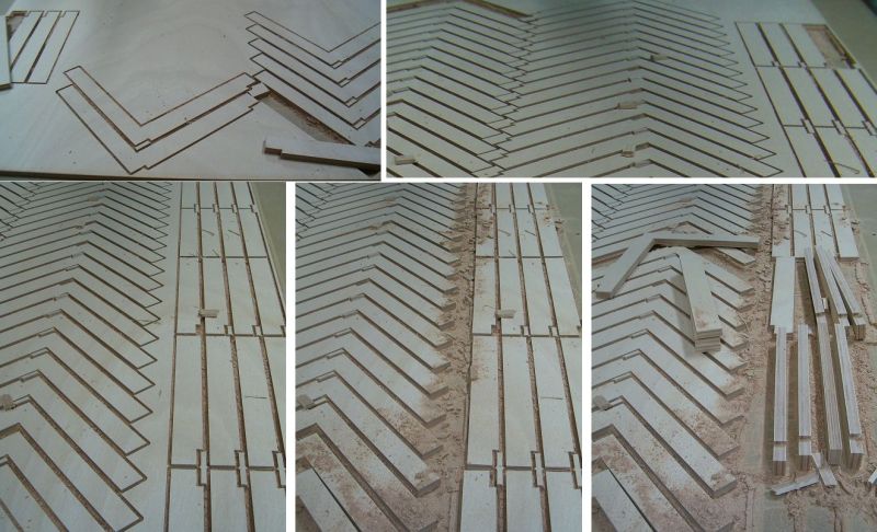
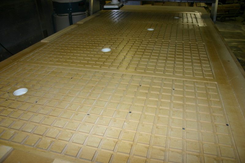
Vacuum grid with 4 zones before spoil board is on, made of MDF sealed with clear
acrylic.
Click here for higher quality, full size image
From contributor G:
Yes, what contributor J has shown looks about right. I cheaped out and used MDF also (the big machines use aluminum or phenolic, as they are more dimensionally stable), and I sealed with epoxy, not acrylic.
I did use more gaps in between the non-machined supports than the above picture. However, that is because I use a plastic top with thousands of small holes, not a bleed through system... Works well if your pump lends itself to needing to be taped off, as I find the plastic is much easier to tape to (and that includes pieces I forgo the vacuum on). Plus, it is more stable that the bleed through MDF, which means I only resurface every few months.
This system is basically used on a 49" x 40" Techno Isel with a shop vac type hold down (needs taping!), and a 15HP regen blower on a 5 x 10 table (usually only quickly covering the extra holes required).
For sectioning, you just leave solid sections on the base to box in an area (or using gasket tape would work too), and make sure it is sealed from other sections. If you are really concerned, I suppose you could mill slots in the bleed-through board and fill with epoxy or similar to make it non-porous on the top of the joint. Again, depends on the vacuum size you have.
From contributor J:
A sheet of 1/2" 4x8 aluminum is about 1300.00 here in the southeast. I will use it on a new machine I have ordered.
When you say plastic, are you using 1/4 plastic pegboard?
From contributor E:
A sheet of phenolic the same size costs about half that. There is a good supplier in Jacksonville, Florida (AGR Fabricators). Best to start with a 3/4" since it will have to be milled down to make it flat once mounted.
From contributor J:
I am definitely interested in using phenolic on my next machine. I will probably mill two 2'x2' and three 2'x4' zones though.
From the original questioner:
Thanks. I guess my question was not as clear as I thought. My table is about 7' by 10' now with the possibility to go to about 14', which I want to do. I would like to know what other companies use for the framework under the top. How is the plastic or MDF attached to the frame? Also the new machines at the tradeshows do not have a gridwork machined into the top. I do not want to use holes, which is what I have now, as it will draw the dust into the vacuum pumps. My unit has a sheet of 1/4" aluminum under the MDF top now with a thousand holes in it that I could use as a base, but it seems to me that it would severely limit the surface area of the vacuum unless big squares were milled into the aluminum or the underside of the MDF at each hole location. I was also told that it is better to not use a thin piece of MDF, as it will allow too much vacuum to flow through the areas that the work is not on top of.
From contributor G:
You are right, you need to filter the pump. How well depends on the type of pump you have.
As for attaching, I used 1) 1.5" MDF (laminated with epoxy), but then just screws (long, 3/16" self drilling/tapping) to attach to the table, which in my case was aluminum slats (CNT).
I can't quite figure out what setup you have, but certainly with the MDF bleed through, the sheet itself stops the dust.
And about the holes versus grooves... The grooves take the vacuum from the hole to the full area of the zone. If the holes you already have do that, then no problem (well, the holes have to be able to pass through the CFM of the pump). If not, you need to have that distribution layer first. I use about 5/32 holes every 5/8". No pegboard. I would lose vacuum pressure with 5 holes!
From the original questioner:
Okay, so what I want is a bleed-through system. I don't want to mess with gaskets and holes, etc. I would rather create more valved sections from below and open only the ones I need. I must be really confused because it seems that all of your responses are talking apples and I am asking about kiwi. Am I just missing something here?
What does all of this set on? My table now is supported from the sides and is a wood framed table below the aluminum which is below the MDF. I want to throw out the wood frame and make one out of steel tubing or light I-beam. It seems to me that one could section off the framework below and attach MDF directly to the top of the framework without any milling or holes or pods or whatever. The vacuum will pull through the MDF and suck down the part. My thinking is that a smaller part will get more vacuum CFM and negative pressure which is needed to hold it while a larger part will have more surface area, so will require less of both.
From contributor J:
Post us a photo of your table and its framework - we could be closer than we think.
From contributor S:
I have a Precix router that I retrofitted with an aluminum 1" grid deck that I machined right on the router. The original deck is 1/4" aluminum with rows of 1/8" holes in it. This type of deck is meant to be used with MDF dropped on it. I think you might not understand that you really need to have a sacrificial board between your main table and your work material. Using MDF as the main table will give you an uneven surface due to deflection caused by the vacuum.
From the original questioner:
Thanks again. Contributor J, I have an older Glentec (or Glenco?) router. They were bought out by Warthog. The frame that carries the carriage is basically two rails running up the Y axis on either side on welded posts. The rest of the table I am going to toss, so a photo won't make much difference.
Contributor S, you seem to be more in tune to what I am trying to do. I also have some other alterations I want to do to the machine as far as hooking up some PC operated controls that are manual now and improving the dust collection, hooking up a digitizer, etc.
From contributor B:
Here is a table design with better flow, but it does take a bit more time to program and machine. This table is 50" x 50", and the channels are cut with a .5 tool, so you have some idea of scale.

Click here for higher quality, full size image
From the original questioner:
I am still confused about this whole thing. Hypothetically, if my steel frame making up my table was sufficiently rigid, and I constructed it air tight with a plate sealing the underside and a sufficient support grid integrated into it at the top so as to not allow the spoil board to flex, why wouldn't I just put my spoil board right on top of that open framework and let the vacuum do its thing without routing all those slots in the top of the table?
From contributor B:
If you don't have the slots, grid, channels or whatever you want to call them, to allow air to flow under the spoil boards or material, the vacuum will be localized, and not spread consistently throughout your work holding area. A grid pattern with generous flow allows panels to lock down faster and consistently.
From contributor G:
That is right - if you have the solid plate below, air pocket/frame in between, with sufficient supports for the table top, then the bleed through top, you are done. Those slots are not in the top of the table (i.e. top of the spoilboard), they are what is removed to make the supports for the table top while still allowing air flow. So, they are not additional to what you say above, but part of that setup (normally). The difference is that normally the table is not a metal framework with a bottom plate and supports, it is normally one thick plate milled out so it acts like the frame and bottom plate.
From contributor J:
The machine you have is a dual drive 6x12 cutting area that has servos. I believe I may even have a photo of it somewhere - it is a great machine! I have one built by the same guy and have another on the way.
The photos I emailed you will show a 3/4" bottom panel. The vacuum grid is on top of that, then the milled spoil board. Mine is divided into 4 zones and I will divide the new machine into 5. I can write a machine ing file for you as you should be using wincnc and running .tap for your file extensions.
Also, thanks to contributor E. I called the Florida company for the phenolic and it was a good call. I will be using this phenolic on my new machine.
From the original questioner:
Hey everyone that responded, thank you. I think I get it now. My confusion is that my machine is built with steel rails on either side running up the Y axis. The table is a 2x6 framework (yes, framing lumber) with a 1/4" aluminum plate on top of it with a 1" MDF board on top of that supported on the sides by some rectangular hollow aluminum brackets that stick in about 4" or so on either side. I want to rebuild the top to get usage of that extra 8 inches in width as well as lower the table some to get more Z and W travel. There is nothing to hold up the table once I remove this frame. I just figured that as long as the under side of the framework was open anyway, just put the MDF right on top of that to maximize vacuum flow. Probably I would put a thin spoil board anyway (maybe 1/8 to 1/4) as I still make a lot of stupid moves on the machine and programming errors that I am sure will put new meaning to the term "performance art."
Do you have to skim the top and the bottom of the spoil board to allow the vacuum to get past the surface of the material?
Contributor J, yes, I love the machine. It is more accurate than I expected it to be for woodworking. When it is working correctly it will usually hold to at least .001" and usually tighter. I am using WinCNC and I program using mostly .tap and occasionally some .doc files. I also have written some spreadsheet programs to generate G-code for things that I do often, but have different sizes or layouts (dados and dovetails). I have an old version of Vector and Vector NC that came with the computer. I bought the machine used about a year and a half ago and have slowly been upgrading it to get it into better condition, as it was neglected for a while. I upgraded almost immediately to WinCNC from the DOS version and bought a new proprietary computer just for the CNC.
It has a Z -7 1/2 horse Colombo spindle and a W- Porter Cable router mounted. I haven't gotten the spindle to use yet as there were some problems I needed to fix, but it runs now, although it may need a rebuild, as there is a slight bearing noise that I am not really thrilled with.
I want to integrate the spindle with the computer to get it operational from the screen (now it is manual only) and get an on and off for the router as well. It never had an emergency shutoff so that is going in too, and I have the digitizer and software but still need to set it up. Right now the vacuum table is the most important, so I can start running parts without having to figure out where to put screws and breaking bits when I am wrong. I would love to step up to a tool changer but I think my spindle is too small to accept one and I don't have the funds right now to take on that. I would love to get the second motor and setup for the Y travel so I can get that bar off of across the table to get more height capability.