Question
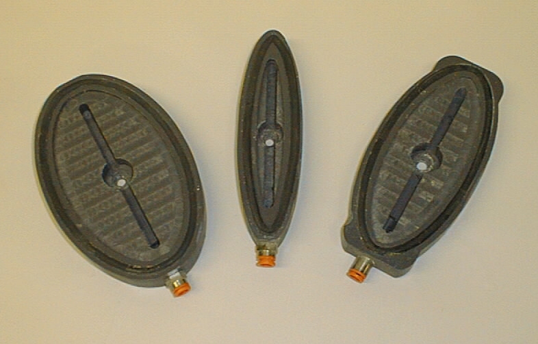
I have a flat table router I'm hoping to start using for door parts, necessitating pods, or the like. I've read all the threads on the subject and would like to manufacture my own, and possibly use a smaller pump to operate them. I like the rubber-top pod idea. Does anyone know what the material is and what the durometer might be?
If I run them off a smaller pump, what size is adequate, assuming good seal? I notice that they are rated by hp, cfm, and other criteria. Interestingly the cfm and hp don't seem to have as direct a relationship as one would expect. I wonder if there is some fudging of numbers going on. Any other advice about pod/system design would be welcome.
Forum Responses
(CNC Forum)
From contributor H:
You really need a soft rubber to seal it up. There have been previous discussions about making your own and using gasket tape to seal up the cup. You can also purchase some ready-made cups from Better Vacuum Cups. In regards to the your question about the vacuum pump. If everything is sealed, you don't need a large pump. It also depends upon what the maximum number of cups your plan to use. If you have a smaller pump and a lot of cups it can take it two-three minutes to get to full vacuum. The larger capacity for the pump, the quicker it builds up vacuum and can handle any vacuum loss.
I would recommend using at least a 10hp pump. I tend to recommend Busch or Becker vacuum pumps. The hp to vacuum isn't related due to the type of vacuum pump. There are different types and some require a more powerful motor.
For a pump I currently run a 5hp Gast pump on a 30 gallon tank. However for years I ran this system with a 3/4 hp Gast pump and a new and "empty" propane grill tank for vacuum storage. A large volume of air pull is not nearly as important here as inches of mercury pulled. I believe the 3/4 hp Gast pump is still available for under $100 from Surplus Center in MN. You will need to add a starting capacitor and a pressure switch but both are available at reasonable prices from Surplus Center. A large volume of air is not necessary because you are only removing air from the manifolds, 1/4" tubing and the small space between the top of the pod and the bottom of the wood.
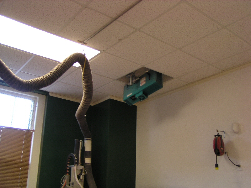
I had a local welding shop put end caps on two 4' lengths of square tubing which I then drilled and tapped for valves - one on either side of the CNC act as manifolds. I run 1/4" tubing from quick connect fittings on each valve to a quick connect fitting tapped into the end of each of the pods. A roll of masking tape hangs on a hook on the end of the CNC for taping the tubing down to the table surface.
Parts positioning is the last part of this equation. I used to draw the parts with a magic marker we keep in T1 on the CNC. We stretch a sheet of 6' wide brown kraft paper over the entire table surface for drawing. We get this from the local cardboard factory as roll ends. We would screw the pods down between the magic marker lines and then put our wood blank in place. If you looked straight down and couldn't see the line we knew the router would cut the part. Now we use an S-L Laser for parts placement but still keep the magic marker in T1 for other uses. This is an incredibly simple to build and efficient to run system. We've cut thousands of our curved moulding blanks with this system over the years.
Second: My S-L Laser shoots the laser lines down onto the surface of the router. With a Point to Point I think we would have difficulty with this process.
Finally: With the flat MDF table surface we can screw the pods down anywhere - even put three right together within an inch or less of each other if we need. This might be an issue trying to do it on a Point to Point.
I picked up my unit as a leftover demo so I acquired it for about 40% off. I looked for a long time before finding this deal and consider myself lucky to have found it. Even with this purchase situation S-L Laser was very helpful in the setup, even giving me a call on the weekend to make sure the installation was going along okay.
The laser program gives you a lot of setup options so you can arrange the screen to meet your needs. I have individual on-screen buttons that correlate to the wood thickness we are placing on top of our 3/4" thick pods. When setting up we first "put the laser on the table" and mount the pods between the projected moulding lines. Then we shift the laser to the top of the wood and set the wood blank on top of the pods. A single mouse click is all it takes to make the change.
You can indeed project more than one part at a time. You are limited by the total number of arcs and lines the laser can keep on the table without them beginning to blink on and off. The laser is fast but it can only do one arc or line segment at a time. If you have a circle or square for example it is so fast you would never see the fact that one segment has turned off while it projects the next segment. It continues around the square or circle repeatedly which makes it look like the entire object is always on.
However if you have a 4x8 sheet with dozens of parts drawn it will project one at a time and you might have to wait a half second for the first one to light up again. When we have large sheets like that we will typically either break it into two or three laser files or just project the four corner images to position the sheet. The laser is also plenty bright but in situations like that it can be helpful to turn the room lights off. I'm not sure of the model number of my unit but it is the standard sized unit - about 20" long and 12" high and 6" thick.
I've never used it but I think the S-L Laser may also read dxf files. If I'm correct then whatever manipulation you do at the router would have to be duplicated in the S-L Laser software.