Question
I designed a cabriole leg for a piece of furniture I have to build using AutoCAD2000. The top of the leg is 2" x 2" and the total width needs to be 52". I think we all know 2" + 48" + 2" = 52". My problem is I'm getting 51 15/16". Am I just having a bad day in CAD or am I doing something wrong? I've redrawn the face frames and the legs several times and am still get the same dimension.
Forum Responses
(CAD Forum)
From contributor C:
I get that once in awhile, too. What I do is stretch the item about .01 or .02 until the dimension reads 52". It will also list it as 52". I guess somehow a tolerance is not set right or something - I really don't know. I just cheat it a hair and move on.
Just the opposite on the middle drawing. On the bottom drawing I made two 2" x 2" squares, same size as the legs, did the dimensioning, and they're dead on the correct dimensions. The top two drawings are done by cropping the legs. I have no clue as to what the problem is - never had it happen before.
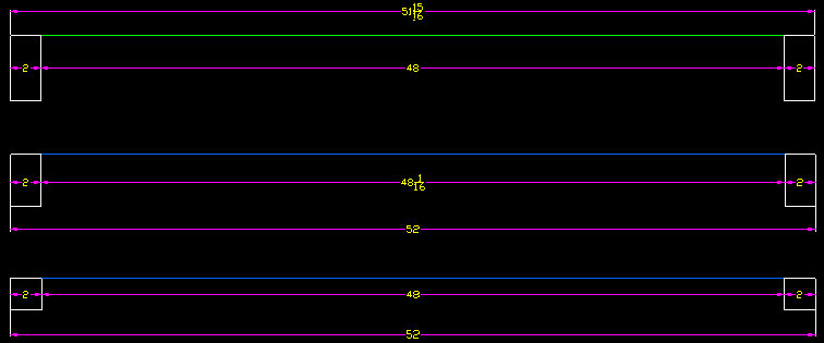
When I measure I get 51 15/16". When I put the blue frames in, I get the correct dimensions and the blue frames connect with both legs. I have no clue as to why it's doing this and it's never happened to me before.
This leg has been worked a lot the last ten years with changes to meet the Chippendale Style furniture designs I do, and I think this caught up with me on this project. She started doing some serious zooming and checking where the knee of the leg meets the post of the leg. What she found is in the images I've uploaded, the one on the right being her redraw of the leg knee.
During all the changes in the leg, I had more or less corrupted it, never even thinking about rechecking the knee after each change. All I was doing was changing the height of the post, and doing this I had gotten where the knee joins the post out 1/16", I guess on a recent change I had made in the leg post. The left side of the post was also 1/16" out. She deleted the post and redrew the knee and put it back where it's supposed to be. She then took the blue frames I drew yesterday and inserted between the two legs at 48" apart. The measurements were then dead on what they're supposed to be.
When I started this design I put the legs at 52" apart outside to outside and then drew the face frames to the legs, not realizing I had a bad leg now. She removed the old legs from the side panels, placed her new leg redraw and those measurements were correct.
Because of both the front face frames measuring 48" and the blue frame being 1/16" longer, it makes us wonder if we still have a problem elsewhere. We're going to take all your suggestions and see what we find.
Now that I've got mud in my face, I've got to got to go buy my daughter a new 27" monitor so she can have more room to correct my mistakes now . Got to love them, and she loves CAD.
