CNC Accuracy - Simple CNC Test Routines
How to run a used CNC through its paces to check on the accuracy and repeatability of its cuts and controls. September 3, 2010
Question
I am purchasing my first CNC router - a 4x8 Northwood unit (3 Axis) - used 1000 hours. It is still under power and I wondered if you could share some simple test routines you would complete and what spec/tolerance you consider acceptable. I do not have a ball bar test available which I gather is the best, however I had planned on doing at least the following with calipers:
1. Cut a 6" circle, measure the radius in each orientation (x and y).
2. Cut a 6" square - inspect 'sharpness' of corners. measure diagonals and lengths.
3. Set up a dial indicator such that the axis can be jogged back and forth 1/2" about start position to look for slop/backlash.
4. Run a small drill pattern (five holes - like the face of a dice) and repeat ten times. Look for positioning deviations.
That's about all I can come up with on my own - what do you think is acceptable for tolerance on these tests? Would you suggest others?
Forum Responses
(CNC Forum)
From contributor Z:
Are you going to be using a particular software to write programs for this new machine?
From contributor M:
Is there a drill bank on the machine? An important test is to verify the relationship between the spindle and drill. I use a bull�s-eye and crosshair pattern to verify I am within about 1/10th of a millimeter in both X and Y. Apart from that, good z control is key in many situations. Understanding where z zero really lies is the key. Also be mindful of the difference between accuracy and repeatability. They are very different things. Six inch squares are really good since you can use a standard digital caliper to measure. I would do a few in different areas of the table to assure they read the same. I generally try to set tools, run parts, and make adjustments and measurements to 1/10th of a mm. In reality I am happy enough with two or three tenths in most situations.
From the original questioner:
The back to back rectangles sounds like a great test. I suppose the larger the rectangle the more easily it is to determine if there is not an exact match. I think maybe I'll go for 20x30". As software goes, I need to still shop for that. I will be manually writing the Gcode for these tests.
Contributor M, thanks for the points you made. Can you elaborate on the bull�s-eye test? I presume you use a carving bit to make the bull�s-eye crosshair/rings (ie. line art) so that the drill hole position is clear. What do you do for a Z zero test?
From contributor R:
Try drilling the same pattern several times, without moving the stock. Look to see if the holes line up perfectly. Draw a couple of rectangles and drill a pattern of four or more holes, sized for dowel pins. See if you can align the parts with the dowel pins inserted into two or more of these parts. Do the doweled parts in different areas of the table.
If you can get close enough on these test parts and assemblies for general cabinet-making tolerances, you will probably be happy with the machine. I have worked on some industrial machines with tight tolerances, and on light-weight, worn-out machines, and, like any other tool you will learn to do good work with what you have to work with.
From contributor M:
I use a 1/8 bit for the cross hairs, a v groove doesn't leave a gullet I can measure with a micrometer. When the space left, right top and bottom is equal I am dialed in. Cut the 1/8 inch groove with a short stiff bit and go slow so there is no wiggle or deflection. Drawn this way there is a half moon at the compass points where the lines meet the routed circle. I measure the smallest distance from edge of the drilled hole to each small half moon.
As far as the z zero test, I have a very good stand to measure the length of my tools, so I can "stage the reference" by cutting a block of Corian to a specific depth. You can only be as accurate as your defined tool length with this method though. Alternatively, if for example you use an HSK63 tool holder you can park the head at a known height then measure the distance to the table directly. Keep in mind that on a spoilboard you are only as correct as the fly cutter cuts. Using the phenolic as z zero in this case is best.
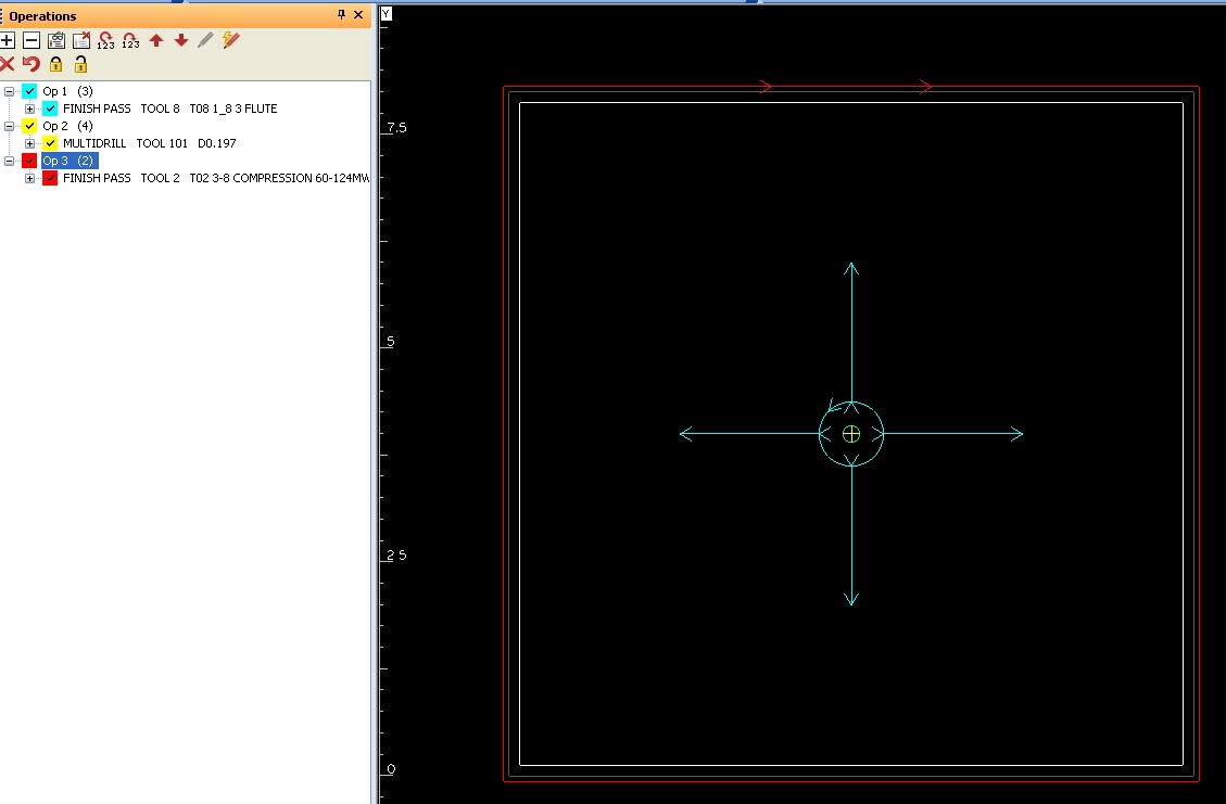
Click here for higher quality, full size image
From contributor Z:
I have to cut tests on new Northwood machines fairly often and I've always found it beneficial to make sure and run gang drill tests for all the different combinations of drills.
From contributor G:
Just a quick note - check more than just the x and y on a circle. At least check on the diagonals too. Doing a diamond is a good idea too as it checks for any issues with axis "harmonics" (for lack of a better word). I wouldn't expect that on such a heavy machine, but it's a quick test.
From contributor B:
The larger the pattern you are cutting the more the drive wear is going to be magnified. Your small circle cuts are not a great test in my opinion. Larger circles on the order of 48" would be better. I like the idea of programming the machine to travel a rectangle pattern almost as large as the machine table. Start at x0, y0 and drill a hole at that point. Then just let the machine transit the large rectangle ten times. When it comes back to x0, y0 at the end of that traveling the bit should still be dead center on the hole.
In addition to traveling a rectangle add in some diagonal and circular movements along the way. Let it go like this for around five minutes and again check the final position alignment at 0,0.
If all this works out well then I'd say you have little or no play in the drive system. All this is of course testing without the stress of cutting. A similar test pattern that would maximize what you can do on a 4x8 sheet and then going back to check your 0,0 location is a good additional step you can take.