Creating a Custom Stair Handrail Volute
Advanced discussion of how to draw and machine a one-of-a-kind volute. June 17, 2009
Question
A friend of mine has asked me to machine him a pair of handrail volutes (I believe that's what it's called - I'm not a stair guy, so please excuse my terminology). I do a lot of 3D carvings, etc. I own a seat of Artcam Pro2009, Visual Mill 6.0 Pro, Solidworks 2009, Rhino 4.0 and CAD.
I need someone to help me with the basic shape of the volute itself - I could use a 2D sketch of the actual curve itself, or the specs of what they typically are manufactured at. I've played with it a little but I can't get it to look right. I'm not asking for anyone's designs, just a step in the right direction.
I have a Shop Sabre CNC router with an HSD spindle and a 4th axis. Nested based machine with MDF spoilboard.
For those of you who manufacture these, how do you do it? Are they 3D carved in multiple setups or is it just one large profile cutter?
Forum Responses
(CNC Forum)
From contributor R:
There is a great book, "A Treatise on Staircasing and Handrailing" by Mowatt, detailing this and many other useful procedures. He gives a generalization on developing veloutes. The rise of the veloute depends entirely on the situation, the height of the newel, the height of the handrail and the amount of turn, the curvature of the rail it intersects, etc.
In plan view, though, you want a smoothly transitioning set of curves. This can be done in several ways, the best of which is a continuous change in radius as you spiral out, but that is hard to draw even on a computer. As a practical matter, most guys make a set of tangential quarter turns, starting with a small radius at the center, and increasing the radius of curvature every 90 degrees. You don't keep all of the centers at the same place; you keep the arcs tangential so they look smooth.
It's not too hard to draw this way. I have laid out many by hand on the bench, as well as several on CAD. It's hard to put this in words, but Mowatt does a good job. The diagram in the book will make it clear.
From contributor J:
The mass produced factory volute is simply a flat circle that loops around to form a cap. As you can see by the Onsrud video, there's really not much to it and it's not very attractive either.
The volute that contributor M is describing is a geometrically correct procedure for drawing and producing the real thing. "The real thing" is not seen too often these days and the book that he is referring to was first published in1900.
The flat factory volute is made in less than half an hour, while a custom geometric volute can require several days.
So your first question may be, what kind of a volute is your friend expecting? There is a big difference between a simple flat part and one that may require one or more complex helical components.
From contributor M:
Here is a recent piece we did. More of a post cap than the standard volute we think of today. We machined this from both sides doing the bottom first, as we only have a three axis machine. This was modeled in Rhino.
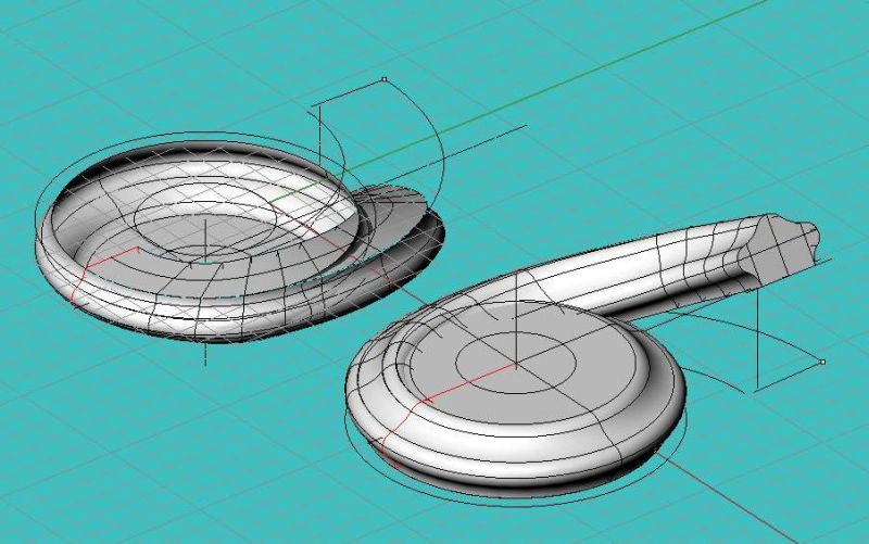
Click here for higher quality, full size image
Finished newel cap before detailing. The center detail is rabbeted in and left loose to hide the fasteners.

Click here for higher quality, full size image
From contributor J:
Very nice, and no, definitely not the standard volute we think of today... But it is a fairly faithful reproduction of a typical vintage handrail termination of the 18th century, reminiscent of New England Cape Cod, usually over a large cylindrical post, suggesting a ships mast? Great example of application of modern technology to re-create traditional woodwork. I like it! (Now, don't you be telling me that you put it over glass or stainless steel.)
From contributor M:
Actually they used a wrought metal rail, but very tastefully done. The rail profile is actually a reproduction we did for a historic building many years ago. You are right, though - if you look in any vintage millwork catalog that profile is there.
From the original questioner:
I can't get over all the responses and help. Thank you for the name of the book; even though it may be older, I'm going to look on Amazon and Borders to see if it's still in print. I love reading stuff like that. It amazes me when you look at how they did that stuff back then - it becomes very humbling. I'm struggling with CAD and a 4 axis CNC router.
I'll have to see exactly what he is after. I found a few on youtube, and like contributor J said, they appeared to be just your everyday high production runs.
Contributor M, very nice job, and thanks for the pics. How long did it take to model in Rhino, and also to machine? How did you machine yours? Did you use a 3D toolpath with a ballnose endmill to hit both sides, or just a 2D toolpath with profiled cutters? What cam software did you use?
From contributor M:
The cap took, I would say, 5-6 hours to model, but I had some weird circumstances going on. This cap sits on a starter type step flowing to a radius staircase, and of course, the newel is the last thing they decided on. I had to hit both a good flow with the bent rail and just the right amount of climb and turning at the same time. So I started with the outline and cut and stacked particleboard full height and used that to get a good determination of the rise while also looking at the flow. Point being it evolved over time, I didn't just sit down and work on it. As far as machining, it took probably 4-5 hours, but there was obviously a fair amount of time prepping the blank. All roughing was done with a long 3/4" upshear and the finish with a 1/4 ball end in an extension using 3D tool paths. The picture is roughing out the top.
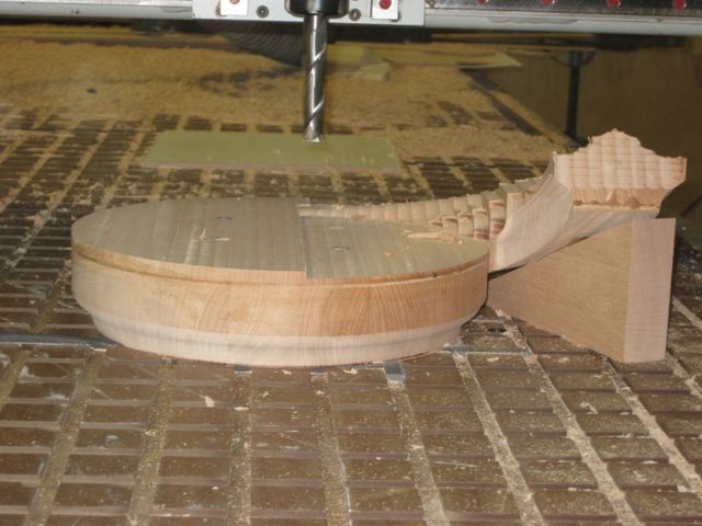
Click here for higher quality, full size image
From the original questioner:
Thanks for posting the picture. From what you're describing, that sounds like a lot of headaches to lay out by hand, let alone try and transfer back into Rhino. You did a very nice job with it.
How did you successfully index the part from machining the bottom half and then flipping over and machining the top half and get everything to line up like it did, especially with the wedge to support the rise of the handrail? Pretty impressive.
Did you use dowel pins or screw holes indexed into your spoilboard? I'm just surprised it worked as well as it did.
That probably was also a bear to get the toolpaths to line up on both sides depending on what cam package you used. I once machined a small propeller just for the heck of it out of walnut just to see if I could do it using Artcam. I had a heck of a time trying to toolpath the opposing side. It worked but it was off a little. I just recently purchased Visual Mill Pro more for the 4 axis rotary toolpathing and it seems much better for that sort of thing, but haven't really had a chance to try it on something like that yet.
From contributor M:
Okay, tip of the day. If you notice in the picture there is gasket material under the part. It is sitting directly over a vacuum port which uses four 1/2" bolts through tapped from the bottom. The bolts sit down low enough we added four indexing pins that we used to locate the part. You can see the holes in top of the wood. As far as toolpaths, the part is mirrored and relocated to do the other side. The 3D toolpaths can only go so deep because they can't under cut the part, so as long as you locate exactly, it should be good. The wedge was "hot glued" in place to prevent any chatter. This part did require some sanding as the locating pins are accurate, but it is still wood.
From contributor D:
Contributor M, what make router do you use and do you use pods a lot or do you make your own fixtures? What HP spindle is your machine and what style pump works for you, HP, dry vane or blower or oil ring? We are getting ready to purchase and would like to get someone's opinion who has done this already. Really nice volute by the way, awesome!
From contributor M:
We have an older 5' x 16' Multicam Pro, 9hp spindle, with 2 x 15hp blowers for each half of the table. We don't have a pod system for the table, but have built a series of home made pods we use occasionally. Our setup is good, but definitely older technology.