Drafting Spirals in AutoCAD LT
An early learner's question about AutoCAD LT: how to approach the problem of drafting a three-dimensional spiral shape. July 29, 2012
Question
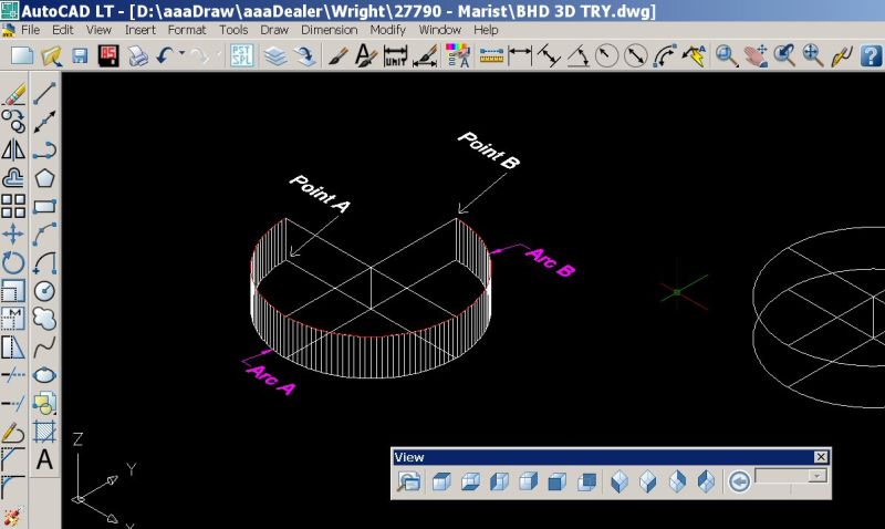
I've done a little reading along the way on using the 3D features available in AutoCAD LT and am trying to get a bit of a handle on how it works. In the photo below you'll see that I've drawn two circles. The lower one is Arc "A" and the upper is Arc "B" which is 3" above Arc "A". Then I trimmed off 90 degrees oof each circle and added 3" of thickness to Arc "A".
I want to draw a spiral curve along the outer surface created by the 3" thickness of Arc "A", going from Point "A" to Point "B". Once done it is that spiral line that I will use in the next step of this little project. I've spent some time reading the help files but have not found info on how to do this. I'm sure it's pretty straight forward, I just haven't found the command procedure. Can someone lend a hand?
Click here for higher quality, full size image
Forum Responses
(CAD Forum)
From contributor B:
You can't do AutoLISP in AutoCAD LT either.
From the original questioner:
That is indeed what I want with the exception that I only need to go 3/4 of the way around one revolution of the coil. Can that be created in LT?
From contributor B:
No I don't believe you can in AutoCAD LT. You can via LISP or 3d Polyline or Helix commands. Just one of the many downsides of LT.
From contributor L:
I am not familiar with LT, but I know that it does not normally have the capability to run LISP programs. That leaves only scripts which are just a sequence of command line commands. I wonder if a LISP command can be performed at the command line. If so, can a line of LISP be embedded in a script?
You could do this manually, although that might be a bit of a pain:
Do a List on your arc to find its length.
Draw a line from the center of your arc to the endpoint of the arc.
Polar array that line around the center of the arc for the number of segments you want +1.
For my example I used 10 segments.
Change you view to 3D Views � Front, or Vpoint 0,-1,0.
Change your UCS to View.
Draw a horizontal line that is the length of your arc.
Draw a vertical line at the end point of the horizontal line that is the height of your
spiral (3 inches).
Draw a line from the opposite end point of the horizontal line to the top end point of the vertical line to form a triangle.
Array the vertical line along the horizontal line for the same number of segments you used for the arc +1. The distance between the lines will be the length of the horizontal line divided by the number of segments.
Trim off the tops of all the vertical lines with the angled line of the triangle.
Do a 3D Orbit to get a convenient view of both the triangle and the arc.
Change the UCS to World.
Move or copy the vertical lines from the triangle to the end points of the lines around the arc.
Do a 3DPolyline (3DPoly) to all of the top end points of the vertical lines around the arc.
From the original questioner:
Contributor L - thank you t
I use the same method without the 3D aspect to lay out an arch top casing in a curved wall. What I didn't know about here was the "3Dpoly" command. It seems though that this will create lines between the rising points as vs. an arc. It looks like you would have to have very short distances between your arrayed vertical lines to end up with a curved like surface? I don't suppose there is a corresponding 3Darc sort of command (which of course does not work). I couldn't find anything other than 3Dpoly in LT help.
From contributor L:
You might be able to turn the 3D Polyline into a spline using Pedit. That might help. How close that comes will also depend on how many segments you have.
From the original questioner:
I gave it a try and you can indeed Pedit a polyline in a 3D view to become a spline. That should solve my small test project.
From contributor B:
If you turn it into a spline the vertices points will not line up with the actual spline though. Here is the 3D Spiral LISP Routine if anyone is interested.
(defun myerror (s) ; If an error (such as CTRL-C) occurs
; while this command is active...
(if (/= s "Function cancelled")
(princ (strcat "\nError: " s))
)
(setvar "cmdecho" ocmd) ; Restore saved modes
(setvar "blipmode" oblp)
(setq *error* olderr) ; Restore old *error* handler
(princ)
)
(defun cspiral (ntimes bpoint hfac lppass strad vfac
/ ang dist tp ainc dhinc dvinc circle dv)
(setvar "blipmode" 0) ; turn blipmode off
(setvar "cmdecho" 0) ; turn cmdecho off
(setq circle (* 3.141596235 2))
(setq ainc (/ circle lppass))
(setq dhinc (/ hfac lppass))
(if vfac (setq dvinc (/ vfac lppass)))
(setq ang 0.0)
(if vfac
(setq dist strad dv 0.0)
(setq dist 0.0)
)
(if vfac
(command "3dpoly") ; start spiral ...
(command "pline" bpoint) ; start spiral from base point and...
)
(repeat ntimes
(repeat lppass
(setq tp (polar bpoint (setq ang (+ ang ainc))
(setq dist (+ dist dhinc))
)
)
(if vfac
(setq tp (list (car tp) (cadr tp) (+ dv (caddr tp)))
dv (+ dv dvinc)
)
)
(command tp) ; continue to the next point...
)
)
(command "") ; until done.
(princ)
)
;;;
;;; Interactive spiral generation
;;;
(defun C:SPIRAL (/ olderr ocmd oblp nt bp cf lp)
;;;;(setq olderr *error*
;;;; *error* myerror)
(setq ocmd (getvar "cmdecho"))
(setq oblp (getvar "blipmode"))
(setvar "cmdecho" 0)
(initget 1) ; bp must not be null
(setq bp (getpoint "\nCenter point: "))
(initget 7) ; nt must not be zero, neg, or null
(setq nt (getint "\nNumber of rotations: "))
(initget 3) ; cf must not be zero, or null
(setq cf (getdist "\nGrowth per rotation: "))
(initget 6) ; lp must not be zero or neg
(setq lp (getint "\nPoints per rotation : "))
(cond ((null lp) (setq lp 30)))
(cspiral nt bp cf lp nil nil)
(setvar "cmdecho" ocmd)
(setvar "blipmode" oblp)
(setq *error* olderr) ; Restore old *error* handler
(princ)
)
;;;
;;; Interactive spiral generation
;;;
(defun C:3DSPIRAL (/ olderr ocmd oblp nt bp hg vg sr lp)
;;;;(setq olderr *error*
;;;; *error* myerror)
(setq ocmd (getvar "cmdecho"))
(setq oblp (getvar "blipmode"))
(setvar "cmdecho" 0)
(initget 1) ; bp must not be null
(setq bp (getpoint "\nCenter point: "))
(initget 7) ; nt must not be zero, neg, or null
(setq nt (getint "\nNumber of rotations: "))
(initget 7) ; sr must not be zero, neg, or null
(setq sr (getdist bp "\nStarting radius: "))
(initget 1) ; cf must not be zero, or null
(setq hg (getdist "\nHorizontal growth per rotation: "))
(initget 3) ; cf must not be zero, or null
(setq vg (getdist "\nVertical growth per rotation: "))
(initget 6) ; lp must not be zero or neg
(setq lp (getint "\nPoints per rotation : "))
(cond ((null lp) (setq lp 30)))
(cspiral nt bp hg lp sr vg)
(setvar "cmdecho" ocmd)
(setvar "blipmode" oblp)
(setq *error* olderr) ; Restore old *error* handler
(princ)
)
From contributor Z:
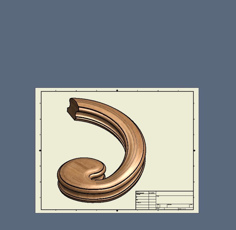
Is this what you are trying to draw? Give up AutoCad and go right to Inventor. Show them what they what to see.
Click here for higher quality, full size image
From the original questioner:
You're sort of on target with your photo. That would be the final product but all I was trying to do here was come up with the perimeter and a top flat surface at this point. Once there then I was going to see if I could extrude the profile along the surface to create a CNC carving toolpath. This is just a bit of an exercise as I doubt I could get the extrusion to work, but who knows. This is really 5-axis work but I'm curious if I could pull it off on a 3-axis machine with carving as vs. a custom bit on a 5-axis machine.
From contributor L:
Whatever method you use, check to make sure that the bottom of the profile remains horizontal and that the profile does not rotate as it climbs up and around the spiral.
