Question
Machine: Andi Exact 51/ Fanuc 18 controller. Alpha Cam
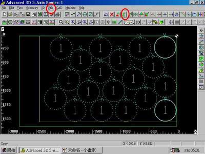
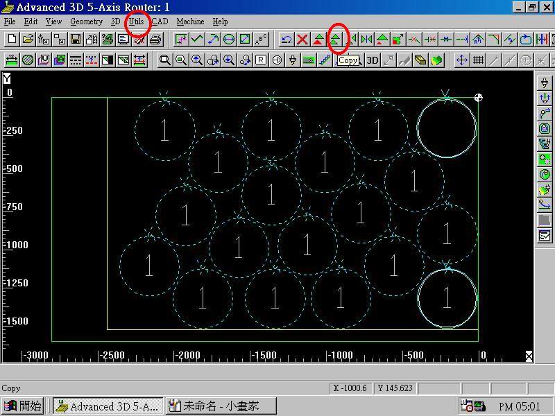
If we are doing a number of code intensive parts that are all the same, say circles, what is the procedure to have the code written once and repeat itself starting at a different xy location? This would reduce the size of our programs. For example, say we want to do 15 -18" diameter circles on a 5 x 8 sheet of MDF.
Also, is there a way to insert a code before a 'M00' to signal a buzzer to let the operator know it's time to flip a part over or clean up the cuttoffs before the next operation?
Forum Responses
(CNC Forum)
From contributor G:
A parametric subroutine is perfect for this application. I work off fagor controllers, so my actual code is different, but you should be able to decipher and apply. It works like this. Go to the location for your first circle or other item and then flag this spot as the beginning of your subroutine. The fogor uses this:
G23 N8
(G23 is beginning of routine and the N8 is the subroutine name - this can be anywhere from N0-N99)
Then switch to incremental programming (G91) and produce one part.
Flag the end of the subroutine with G24.
Switch back to absolute (g90).
If the shape of your part is extensive, this works wonders. It also works well if you have to make several passes around the same part.
In all, it looks like this:
(MOVE TO 1st LOCATION)
G23 N8
G91
(HERE ARE YOUR LINES OF CODE)
G24
G90
(MOVE TO NEW LOCATION)
G21 N8.1
(MOVE TO NEW LOCATION)
G21 N8.1
(MOVE TO NEW....ETC.)
I do have a few questions, however. I assume a standard row/column layout isn't acceptable, as it surely doesn't give a very nice yield? (You want staggered rows?)
How do you typically hold the parts down? Vacuum alone?
We run an Andi/Fanuc 11/AlphaCAM here as well.
What I need to know is how to do something like the post above. A 'repeat at x##,y##' procedure. The reason for all of this is that we could economize our controller memory as we keep a number of daily programs in the machine, and still have room for specials.
The first loop...
1 - set a "counter" variable=0
CountA=0
That's your "inner" loop. If you set the conditions right, this will net you any number of circles side by side. Every time the counter goes up one, the G52 shift goes up one more time and the shift gets bigger and bigger. First it shifts 200mm, then 400mm, then 600mm, etc.
The main thing to watch is when you go to repeat this loop, you must *not* repeat the line which sets the counter to zero. Obviously, the condition you set to exit the loop will never be met if you make this error. Here's some code:
N1
COUNTER=0
N2
G52 X-(COUNTER*200)
*cut paths*
N3
IF COUNTER=5 GOTO END
COUNTER=COUNTER+1
GOTO 2
END
This simple loop will execute your program six times (never forget the time the machine cuts when the counter is set to 0), shifting 200mm to the negative in x each time. Note that when the program repeats, it does *not* repeat the step of setting the counter to zero.
I'll let that sink in and do the double loop in another post, then I will try a real double loop on my machine since the code should be near identical.
I don't know how big your table is, so I placed the circles 1/4" from the right and rear edges of the machine.
The main program goes to each start point in succession, working from left to right and back to front. At each start point, the subprogram is called (M98) and executed. At the end of the subprogram, control is returned to the main (M99) which proceeds to the next start point.
The subprogram makes a 1" move to turn comp on and ramp through the material to cutting depth, then another 1" move to the top and center of the circle. The G02J-9. block makes one complete circle of 9" radius. (If you aren't familiar with I & J codes, look them up in your manual - to me it's the simplest way to make full circles.) The circle is followed by a 1" move away from the part and another 1" move to ramp up and out.
This is the basic manual programming style that we used for years prior to CAM software. Using subprograms can save a lot of space when you have multiple parts on the table, especially if the shapes are complex. It also simplifies tweaking as you only have one subprogram to deal with as opposed to multiple occurrences within the main. If you have Macro-B (Fanuc option) enabled on your control, you could make this program shorter as well as parametric. You could actually have the program figure how many circles fit based on the circle diameter and sheet size used!
These days we mostly use CAM'd programs, as it is much faster and more accurate (no math errors or typos!). Memory is also cheap, so program size isn't really a factor.
Anyway, try this out and see if it works for you.
O100(18 IN CIRCLES - MAIN)
(TOOL 1 - 1/2 STRAIGHT -G54-H11-D1)
-
-
SAFETY BLOCK
AND
SPINDLE SELECT, START, ETC.
-
-
G54G90G0X-7.25Y-.25(START POINT OF FIRST CIRCLE TOP ROW)
G1G43H11Z.50F200.(TURN ON HEIGHT OFFSET - BRING TO .500 SAFETY PLANE)
M98P105(CALL SUBPROGRAM)
G90G0X-26.Y-.25
M98P105
G90G0X-44.75Y-.25
M98P105
G90G0X-63.5Y-.25
M98P105
G90G0X-82.25Y-.25
M98P105
G90G0X-82.25Y-19.(FIRST CIRCLE SECOND ROW)
M98P105
G90G0X-63.5Y-19.
M98P105
G90G0X-44.75Y-19.
M98P105
G90G0X-26.Y-19.
M98P105
G90G0X-7.25Y-19.
M98P105
G90G0X-7.25Y-37.75(FIRST CIRCLE THIRD ROW)
M98P105
G90G0X-26.Y-37.75
M98P105
G90G0X-44.75Y-37.75
M98P105
G90G0X-63.5Y-37.75
M98P105
G90G0X-82.25Y-37.75
M98P105
-
-
SHUT DOWN - GO HOME
-
-
M30
O105(18 IN CIRCLES - SUBPROGRAM)
(STARTS 2" RIGHT OF TOP OF CIRCLE)
G91G1G42D1X-1.Z-1.30F200.(COMP ON - RAMP DOWN)
(Z VALUE REPRESENTS SAFETY PLANE & 3/4 BOARD & THRU CUT - .50+.75+.05=1.30)
X-1.F400.
G02J-9.(FULL CIRCLE - J VALUE DEFINES RELATIVE LOC OF CENTER POINT)
G01X-1.
G40X-1.Z1.30(COMP OFF - RAMP UP TO SAFETY PLANE)
M99(RETURN TO MAIN PROGRAM)
Just for fun, here's an old (note the date) hole macro that we used to leave resident in the control and was used by many of our old programs. Variables were passed to it when calling from the main program: G65P4028A0D2.25F200.H1R.5T3.Z.50
Note that if "H" is set to zero it simply cuts the inside perimeter of the circle. If "H" is set to 1 it will hog out the entire hole starting at the center.
Don't ask how I came up with 4028 for the program number - I have no idea!
O4028(HOLE BORING)
(VERSION 1.2 - 08/19/89 - HOGS OUT CENTER OF CIRCLE)
(TO HOG OUT CENTER OF HOLE SET H TO 1 WHEN CALLING MACRO)
(START POS SHOULD BE OVER CENTER OF HOLE)
(A=#1=DIAMETER ADJUSTMENT)
(D=#7=DIAMETER OF HOLE)
(F=#9=FEEDRATE)
(H=#11=SET TO 1 TO HOG CENTER)
(R=#18=RAPID TRAVEL DIST TO WORK SURFACE)
(T=#20=OFFSET # FOR TOOL RADIUS)
(Z=#26=DEPTH OF HOLE FROM WORK SURFACE)
#2=#5001(X START POS)
#3=#5002(X START POS)
#4=#5003(X START POS)
#12=#[2000.+#20](READ DIA OFFSET)
#10=[#7/2-#12]+[#1/2](CALC RAD AND ADD ADJUSTMENT)
IF[#11EQ1.]GOTO100(HOG CENTER?)
G91G00X[#10-.03]Z-[ABS[#18]]
G02I-[#10-.03]Z-[ABS[#26]]F#9
G01X.03
G02I-#10
X-[#10*2]I-#10Z[ABS[#26]]
G90G01Z#4
X#2Y#3
GOTO500
N100#21=[#12*.9]
G91G00X#21Z-[ABS[#18]]
G02I-#21Z-[ABS[#26]]F#9
I-#21
#23=#21
#22=#21*2
WHILE[#22LT#10]DO1
G01X#21
G02I-#22
#23=#22
#22=#22+#21
END1
G01X-[#10-#23]
G02I-#10
X-#10Y#10I-#10
X-[#10*.9]Y-[#10*.9]J-[#10*.9]Z[ABS[#26]]
G90G01X#2Y#3Z#4
N500M99
Here's the first loop again:
N10
COUNTER=0
N20
G52 X-(COUNTER*200)
*cut paths*
N30
IF COUNTER=5 GOTO END
COUNTER=COUNTER+1
GOTO 2
END
I'm going to change the line numbers only by adding zeros so I can add the second loop.
What you have to remember about the second loop is you want to repeat the *whole* first process. Again, watch where you send the program so the counters get reset properly. For the next loop, which will do the columns, you *do* want the first loop counter reset to zero so you get all the rows.
COUNTER1=1
N10
COUNTER=0
N20
G52 X-(COUNTER*200)
*cut paths*
N30
IF COUNTER=5 GOTO 40
COUNTER=COUNTER+1
GOTO 2
N40
G52 Y(COUNTER1*200)
IF COUNTER1=3 GOTO END
COUNTER1=COUNTER1+1
GOTO 10
END
It's hard to see properly in this little window, so I will write the code for a real program and try it. Can you provide the cutting code you have now?
I think you can see once you learn how to program loops that you can do a lot of things with short programs. Much better than a subroutine program as was posted above. One of the reasons is that by editing (or making them variables) the two numbers that govern rows and columns, you can change those quantities easily. For smaller parts there are way fewer lines when using loops.
It looked like this: G65H02P#102Q#101R.500
It means add .500 to var #101 and store in var #102
G65 = This is a macro statement - every macro line started with this
H02 = Operation is addition - each operation had its own H code
P = Where to store the result
Q = First number to add
R = Second number to add
Glad we don't have to do that anymore!
P.S. It's much easier to type your message in Notepad than paste into the little message window.
BE CAREFUL IF YOU TRY THIS UNEDITED---> TEST TEST TEST! he he
I just ran this and it works. Note the few 'syntax' things the FANUC requires with brackets and EQ for equals, etc. It cuts 3 rows of 15" circles on a 5 x 8 sheet with a 1/2" tool. I left 14 mm between parts.
Hope this helps:
START
'(SHEETOF15INCIRCLES)
%
O3333 (SHEETOF15INCIRCLES)
G17 G90 G21 G40 G80
\M68
G08 P1
M06
'(OP 1 FINISH PASS TOOL 101 1_2 COMP)
'(EFFECTIVE DIAMETER 12.7)
N1 (TOOL #101)
(1_2 COMP - FINISH PASS)
T101
M5
M11
#111=1 (ROW COUNTER)
N2
#122=0 (COLUMN COUNTER)
N3
G52 X-[#122*395]
G0 G90 G54 X-130.157 Y-1160.915 M13 S18
G0 G43 H1 Z100.
G0 Z40.
X-130.157 Y-1160.915
Z25.
G1 G42 D33 X-193.137 Y-1133.124 F1500. Z0.
G3 X-304.675 Y-1098.475 R196.85 F6000.
X-501.525 Y-1295.325 R196.85
X-304.675 Y-1492.175 R196.85
X-107.825 Y-1295.325 R196.85
X-193.137 Y-1133.124 R196.85
G0 Z40.
IF [#122EQ5] GOTO 4 (NUMBER 5 IS THE ROW CONTROL)
#122=#122+1
GOTO 3
N4
G52 Y+[#111*395]
#111=#111+1
IF [#111EQ4] GOTO 5 (NUMBER 4 IS THE COLUMN CONTROL)
GOTO 2
N5
G17 G91 G28 Z0 M95
M92
G08 P0
\M07
M69
G91 G28 Z0
G28 X0 Y0
G52 X0 Y0 Z0
M30
%
I travel at 40 mm above the table and rapid to 25 mm when the sheet is 19 mm as it was programmed here.
I assume no responsibility for crashes! Test this first, please use z-lockout, etc.
START
O0001
G91 G28 X0 Y0 Z0
G90 G40 G49 G17 M92
M06
M13 S18(12MM FLAT)
M11
G90 G54
G0 G43 H1 Z70.
X2222.4 Y415.5
M98 P2
G0 X2222.4 Y837.
G52 X0. Y421.5
M98 P2
G52 X0 Y0
G0 X2005.95 Y1183.5
G52 X-216.45 Y768.
M98 P2
G52 X0 Y0
G0 X1872.6 Y625.65
G52 X-349.8 Y210.15
M98 P2
G52 X0 Y0
G0 X1768.05 Y1515.
G52 X-454.35 Y1099.5
M98 P2
G52 X0 Y0
G0 X1656.9 Y972.
G52 X-565.5 Y556.5
M98 P2
G52 X0 Y0
G0 X1522.8 Y415.5
G52 X-699.6 Y0.
M98 P2
G52 X0 Y0
G0 X1419. Y1303.5
G52 X-803.4 Y888.
M98 P2
G52 X0 Y0
G0 X1306.5 Y762.
G52 X-915.9 Y346.5
M98 P2
G52 X0 Y0
G0 X1093.35 Y414.
G52 X-1129.05 Y-1.5
M98 P2
G52 X0 Y0
G0 X1068.6 Y1093.5
G52 X-1153.8 Y678.
M98 P2
G52 X0 Y0
G0 X1069.95 Y1515.
G52 X-1152.45 Y1099.5
M98 P2
G52 X0 Y0
G0 X855.45 Y745.5
G52 X-1366.95 Y330.
M98 P2
G52 X0 Y0
G0 X719.7 Y1305.15
G52 X-1502.7 Y889.65
M98 P2
G52 X0 Y0
G0 X617.55 Y414.
G52 X-1604.85 Y-1.5
M98 P2
G52 X0 Y0
G0 X506.4 Y957.
G52 X-1716. Y541.5
M98 P2
G52 X0 Y0
G0 X369.75 Y1515.15
G52 X-1852.65 Y1099.65
M98 P2
G52 X0 Y0
G0 X268.5 Y625.5
G52 X-1953.9 Y210.
M98 P2
G52 X0 Y0
M92 G0 G49 H0 Z0.
M95
G91 G28 Z0
M07
G91 G28 X0 Y0
M30
O2
G0 Z20.
G1 Z-12. F3600
G3 X2234.4 Y403.5 R12. F5000
G2 X2404.595 Y108.786 R196.5
X2064.205 R196.5
X2234.4 Y403.5 R196.5
G3 X2246.4 Y415.5 R12.
G0 Z30.
M99 (END OF SUB 2 )
%
You can buy a sensitive detector (people use for their cat or visitor) at Walmart or K-Mart. Place it on machine zero point. Cheap and easy!
Comment from contributor T:
Way too much manual work! Try this:
Write a program that starts nozzle at the corner of your material and homes every axis but X and Y, then calls out another program and then homes the machine again. This will be your main program.
O1513(MAIN)
N0001 G91 G28 Z0.0
N0002 G28 A0.0 B0.0
G90
G92 X9.25 Y.25 Z11.5 A0.0 B0.0
(AT THE NEXT LINE YOU'LL SEE P51514)
(THE FIRST 5 TELLS YOUR SYSTEM HOW MANY)
(TIMES TO CALL OUT PROGRAM# 1514)
M98 P51514
N0003 G91 G28 Z0.0
N0004 G28 A0.0 B0.0
N0005 G28 X0.0 Y0.0
M30
Write a row movement program that calls out your part program and sets the row movements.
O1514(ROW MOVEMENT)
(IT CALLS THE PART PROGRAM X NUMBER OF TIMES FIRST)
(IN THIS CASE IT'S 3 TIMES)
M98P31515
G91
G28 Z0.0
G28 A0.0 B0.0
G91
G00 X-18.0 Y54.625
G92 X0.0 Y0.0
M21
M99
Now write your part program.
O1515(PART PROGRAM)
G90
G52 X0.0 Y0.0 Z0.0
N0006 G00 X0.0 Y0.0
N0007 G00 Z0.0
(START LEAD IN)
G90
G01 Y-0.125
G02 J-9.0
(POWER OFF)
M98P8000
N0008 G00 Z0.0
(THE NEXT LINE IS A MOVE TO THE START POINT OF YOUR NEXT PART)
N0009 G00 Y-18.125
N0010 G00 A0.0 B0.0
N0011 G92 X0.0 Y0.0
M99
When the part program finishes, it will repeat the number of times you specified moving to the location of the next part, which you also specified at the end of the part program. The part program will then exit back to the row program and finish running there, which moves your tool to the top of the next row. The row program finishes and runs again because you told it to run 5 times in the main program. The first thing in the row program is a call out for the part program which again runs 3 times. The entire cycle repeats until all repetitions have run and the main program finishes and exits.