Question
I turn quite a few newels and balusters and occasionally turn newel caps to match the profile of my customer's handrail. How do you cut the pie shape out of the cap?
Forum Responses
(Architectural Woodworking Forum)
From contributor J:
Man, this is a tough one because of the size of the post; my gut feel was a cope cut, only other thing would be a big router bit and router. Either one of these, I think, requires a shop rather than a hand cut. I am sure there will be a far better answer than mine.
You can do this all with measurements, without knowing the angles, because if you know the length of the sides of a triangle, the angles all take care of themselves, and will be congruent.
However, once you start to fit and pare the angle into the pie-cut, if the profile is different from the side of the easement, you may want to go back to the faceplate and tweak the profile of the cap, so the edges of the two profiles match up.
Thanks, contributor S, for the detail. I think if the cap is made correctly and the mitre is right the profile should all line up. Nice in theory, isn't it?
Rather than spending my hard-earned free time to come up with a rigorous mathematical expression for the shape of the cut (a parabola?), the band-saw cut and chisel-trim approach might take a little less time if you keep the basic shape of the diagram in mind to know where to start trimming.
Comment from contributor R:
From contributor K:
In your first drawing, the side elevation above, it looks to me that the height of the rail at 1 1/8" needs to intersect the pattern at the fillet like it is drawn. If you shorten that angle like you just did, the point of your miter will be ending at a height above the pattern turned on the cap.
From the original questioner:
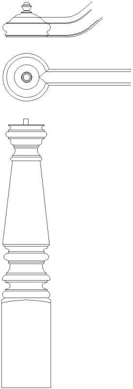
The drawings are of two different rails and caps. The rail in the top drawing is larger than the rail in the bottom drawing, but the principle is the same. If the rail is 2 1/4", the rail profile on the cap will not be deeper than 1 1/8" (unless it has been turned improperly), and so for the rail profile to match the cap profile, the cut should not be deeper than 1 1/8".
From contributor V:
I think this might help a bit. The handrail is a little bigger, but you can see how the rail is cut into the cap. It's not as easy as one may think. Even in my drawings, some of the profile points didn't hit right on. One other point of interest - the depth of the "V" in the cap should be laid out from the edge of the rail and not the center line.
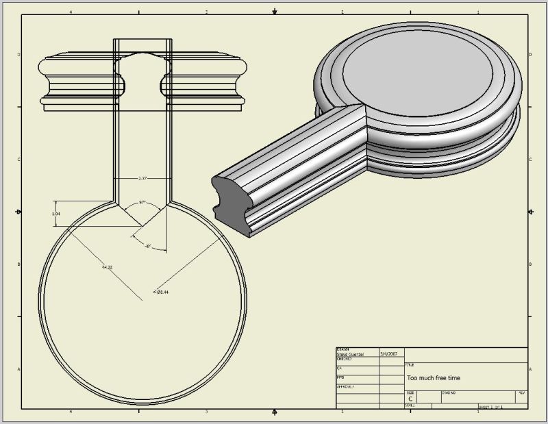
Click here for higher quality, full size image
From contributor B:
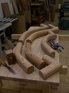
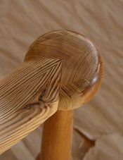
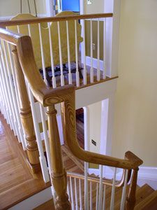
The following images show the miter in the ball of the newel and this was cut by hand on site. First cutting the rail on a miter saw, then marking the newel off the rail, cutting the ball with a backsaw and slowly refining the cut with chisels. This certainly is not as detailed as your newel, so I could fudge the curvature of the ball and rail with rasps. Leaving a little extra wood to play and refine is always a good idea as in tilting the newel outward with a press fit from the rail creates a snug/snap connection, then the fasteners are just securing that fit. Certainly the point of the miter does not coincide with center of the newel.


From the original questioner:
Beautiful job. It looks like your handrail is coming into the ball at an angle. Is this right?
From contributor B:
Thank you! The rail and newel meet close to a horizontal plane as shown in the top picture. What might give a different perception is that the top of both the rail and newel are rounded, so there is no real top "flat" surface, so everything is tapering from and to the miter. There are a lot a variables that can effect the miter, i.e. how the rail is attached at the upper end, at what height, if the balusters are correctly cut and placed. I would reserve the final tweaking of the miter for the site work, just in case.
From contributor V:
You'll see that you can not get all the profile to line up perfect. It is close enough to work with some carving and sanding. I think the cap being a circle and the lines traveling different lengths around the circle throws off the final fit.
From contributor I:
Miter cuts work if the profiles match. I once, at the client's insistence, had to join a rail and newel cap of different profiles. After scratching my head, I had the turner make an extra cap, coated it with yellow glue and loose 60 grit abrasive, and chucked it in the drill press to use as a coping head after hogging out the rail ends with the bandsaw and gouges. I got an acceptable fit, though only because the profiles were simple curves in the area of intersection.
From the original questioner:
Wow, now that is clever. Pretty cool idea!
From contributor Z:
The pie shape will not be a straight cut. In the diagram, I did a simple mapping of the contour to the intersections of the inner and outer diameters of the cap and an arbitrary width hand rail of the same straight contour. The "V" cut in the cap will be concave (cupped) and the end of the rail will be convex (blunt). For the same width of rail, and inner and outer diameter of the cap, the shape of the pie cut will be constant - regardless of the actual contour used.
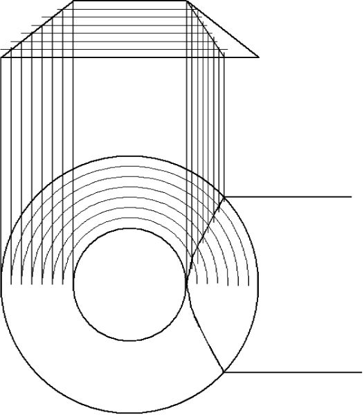
Click here for higher quality, full size image
From the original questioner:
I don't know that I understand how your drawing works, but intuition tells me you're right.
From contributor X:
Any time you mitre a straight molding to a curved one with the same profile, the true mitre's got to be curved (I know it's not a section of a circle; I'm thinking it might be a section of a hyperbola). You've got three choices: Make the moldings slightly different, so the true mitre is straight. Figure out the true mitre, and cut both pieces on the curve. Or cut a straight mitre so the edges line up and fake it. That's what we do with newel caps. We draw a full-size picture on 1/8" plywood to get the angle right - it's not 45 - and screw the plywood to the center of the cap. Then cut through it on the half of the line on the band saw. After the joint is assembled, we tune it up with sharp carving tools and sandpaper.
From the original questioner:
Are you saying that you mark the proper angle on the plywood and then fasten it to the top of the cap to use as a guide?
From contributor X:
Yeah, now I draw the pattern on Autocad, print it out, and spray contact it to the scrap of 1/8 or 1/4 plywood, but it can be drawn right on the plywood too. We screw through the center of the plywood into the center of the cap, and saw through the plywood and cap on the bandsaw. We align the grain on the cap with the grain on the rail because this makes it easier to carve. On the pattern, the rail centerline goes through the center of the cap and the point of the joint occurs where the centerline is 1/2 of a rail width in from the outside diameter of the cap. This is for round caps. On square caps, the mitres are 45 degrees, but we cut them with a pattern on the bandsaw too.
From the original questioner:
I guess what I'm missing here is how to fasten a piece of plywood to the top of a newel cap. If you look at the drawing of my cap at the top of this page, it has a small sphere at the top. No place to screw a piece of plywood to.
From contributor G:
I would be tempted to try some sort of holding jig on the sliding tablesaw with the blade tilted to suit your angle of cut. It works fine doing tread returns. But do let us know how it turns out!
The comments below were added after this Forum discussion was archived as a Knowledge Base article (add your comment).
I have always coped the end of the easing or straight rail that will receive the cap. Be sure that your coping tooling total diameter does not exceed the total diameter of the cap.
Comment from contributor M:
I have worked my way through this problem and have come up with my own solutions for the cap profile problem and the miter cut. Copy and paste into your browser.
https://www.youtube.com/watch?v=o4Zs4-rewQY
https://www.youtube.com/watch?v=CTVwi7NpuXE