Question
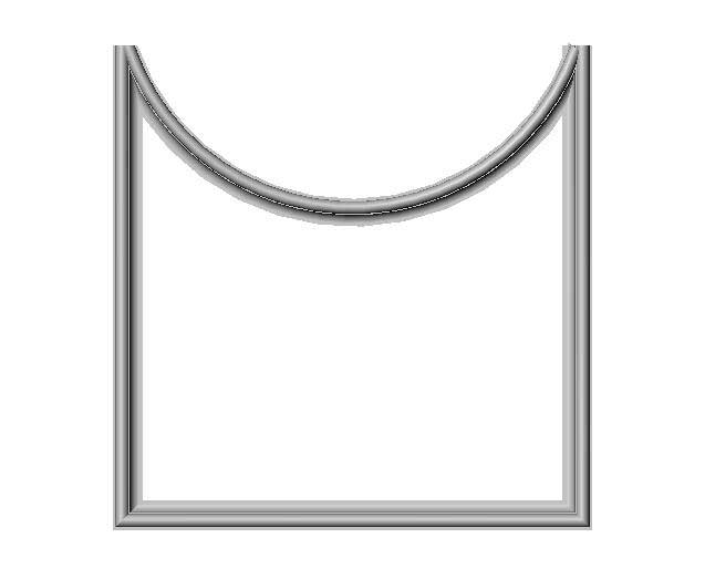
Is there a good way of figuring out the angle for joining a round to a straight molding like this in such a way that the detail matches? Any help is appreciated.
Forum Responses
(Architectural Woodworking Forum)
From contributor K:
For situations like this, I simply place the straight moulding on the wall in it's final location and trace around it with a pencil. Then I remove the straight moulding and do the same with the radius segment. I then transfer the intersection of the lines on the wall to the edges of the radius moulding. I remove the radius piece and place the straight piece back on the wall and transfer the intersection of the lines to it as well, and just connect the lines on each piece and cut to the lines. You should be in good shape and the profiles should match perfectly.
The reason straight miters resulting from the overlapping of the two molds doesn't work is due to the changing shape of the profile as it curves past the straight piece miter - by the time you get to the outside tip of the curve, it has curved away from the line established at the inside of the joint, hence the banana.
Another strategy is to make the curved mold straight at the point that the miter begins - if it won't be obvious. In practice, we just adjust the miter to where we can easily sand/carve the difference and go with it. This is what we do almost daily. It does help if you can design the molding to help minimize this dilemma.

If you standardized on several lengths for the curved molding, you could go one step further and make a 4-cut jig set (L&R x Straight and curved) for each length so there would be no thinking required during the installation.
I have not seen a formula for this, but I would like to. One true arc from the inside corner of the miter to the outside corner does not intersect exactly everywhere that the details within the moulding come together. We find one that is the closest and requires the least amount of sanding, and go with that. If it is still severely off, we cut different arcs, or lines, along the miter that do intersect well at the details. For both ways we sometimes do it on the CNC router.
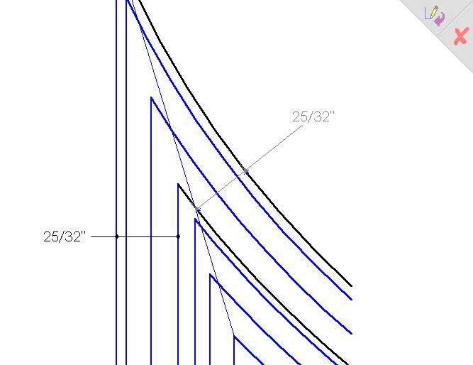
This curve is obtained by drawing the two at full scale in their respective relationships to each other and drawing their various elements such as steps, etc. If there are large unbroken areas draw a series of evenly spaced parallel lines in those areas in exactly the same locations with regards to the moldings edges in both the straight and curved sections.
Now connect these points with straight lines. The resulting curved dotted line is the curved miter that will bring the best results. You can use a compass trial and error until you get a setting as close as possible to the dotted line.
Comment from contributor H:
So here�s my spin on it. I used layout board (similar to the back of a note book, comes in 4x8 sheets) to make templates of each curve and intersecting leg, laid them out and made a corner to corner cut. Taped the joint together laid it on top of another piece of layout board, tacked it to a scrap of ply and cut out the footprint of the corner. I then cut slices of the moulding, traced their profile onto the template and ran the high points of each detail using a compass as a scribe.
Then as described in the drawings and articles above, intersected the points and cut it with a very sharp utility knife. If it's a little dull it will tear the card board, so lots of fresh blades on hand. I then took them and traced them in pencil onto 1/4 MDF, then I cut off the waste and cleaned them up on a spindle sander. I made the template oversized on the back of the molding and past the front edge of the joint to accommodate the base of my trim router.
I turned the molding over and placed the template on the back and tacked it with a micro-pin nailer, clamped it to the table, trimmed the waste with a jigsaw, leaving 1/16 and trimmed it with my router and viola - a perfect miter.
Editor's Note: RT Machinery (website) sells a wide variety of new and used machinery, with ever changing inventory.