Modeling Compound-Curved Casing
CAD users puzzle out how to render a complex curved moulding shape. March 26, 2008
Question
I am trying to draw a solid model of a piece of casing that follows a compound curve. We have made casing like this before by bending to a form and adding the profile. I now want to be able to draw this accurately in AutoCAD 2007 so I can create a CNC program in AlphaCAM to cut this out of solid wood. I am able to successfully extrude this around a compound curve and almost get the results I want. There is one hitch, though. If you look at the image, you will see that the casing does not have the twist it needs to follow the contour of the wall. You will see that it becomes imbedded into the wall more and more as it continues down. This casing sits up against the wall as it should at the top of the arc, and does twist somewhat, but not enough. I have tried loft also. I understand how this trim is supposed to twist as it follows the wall, but cannot figure out how to draw it as a solid model. Anyone know how to do this in AutoCAD? Maybe as surfaces instead of solids?
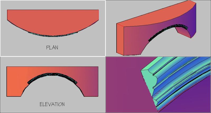
Click here for higher quality, full size image
Forum Responses
(CAD Forum)
From contributor L:
I think if you are able, it would be easier to program it directly in Alphacam. Especially seeing how it is going to be machined. Sometimes importing surfaces from AutoCAD into Alphacam can be quirky and you would need to clean it up a little anyway. If you don't have Alphacam in house and are sending it to someone, then I understand the need. However, you might be able to get away with just sending the geometry with the profile. I would hate to have to do more work than needed.
From contributor Y:
By using the loft command, draw the arch in half (like left hand side) then mirror it and use the Boolean operations to unite the solids. By the way, that is quite the compound curve arched shape you're trying to achieve. Make sure the CNC can reproduce it. You might want to machine it in pieces.
From the original questioner:
I do not have AlphaCAM yet. We are in the process of getting it and this would be one of our first programs for it. (I know this is a bit of a plunge into it for starters.) I have been told that it is easier to draw in AutoCAD and import into AlphaCAM. Does AlphaCAM have the capabilities of drawing this easily? Does it have some drawing tool for this type of compound curve that AutoCAD doesn�t?
I originally drew this as two halves and used union to join them. I started at the top of the arch, and extruded it down a spline I created by exploding the 3D solid of the wall.
You're right, this is a bit of a challenge, but we do a lot of crazy stuff like this. My CPU is having a hard time with it. Takes forever to process. From what I understand, if I can draw it in a solid or surface, AlphaCAM can handle it. Maybe I should be asking the experienced AlphaCAM users out there if it can be done. Anyone run into something like this?
From contributor T:
There are other CAM products that you might consider if you will need to do the solid model import from AutoCAD on a regular basis.
From contributor L:
I have been programming Alphacam for years and have done plenty of this stuff. For the majority of engineering, AutoCAD is superior. But when it comes to 3D surfaces, I find Alphacam a whole lot easier. I'm not saying it's better (I really don't want to start something with AutoCAD users who do phenomenal 3D work). I'm just saying I find it easier.
It is a simple click to import .dwg or .dxf files but a lot of the time surfaces are not interpreted as well as I have wished. Alphacam does have an option to make this surface easily. I'm not sure if AutoCAD has the same option - I've never seen or needed it. All I would need is the 3D curve and the molding profile to get this done. There are plenty of smart guys here to tell you exactly how to do it through AutoCAD, but I find it easier to draw it in Alphacam if I am going to machine it.
From contributor B:
We typically do this kind of moulding a couple times a year. The hard part is making up the blank, not the profiling. I've always said that a CNC can do most anything, but isn't always the best tool for everything. This is one of those projects I would not bother to try and set up on the CNC. It is not at all difficult to profile something like this on a small moulder like the Williams and Hussey with the correct setup. Trying to precisely mount a compound curve on the CNC for either an aggregate or C-axis moulding head just seems much more complex in terms of programming and positioning than it is worth.
From the original questioner:
I got it. I was able to use the loft command and the guide line feature to create a surface.
From contributor Y:
Your post made me think how difficult this can be in AutoCAD. Well, it is not easy, but it is possible. I used AutoCAD 08 and the command "Sweep" to achieve this. I drew the arch in solid and then copied the edge I wanted to use as a path. I had my profile in the center of the solid arch in a vertical position and I use the "sweep" command to draw half the arch. I then mirror it, and here it is.
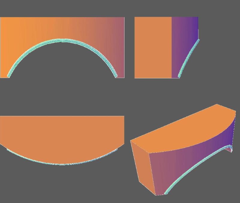
Click here for higher quality, full size image
From contributor Y:
Oops - just saw your post. Glad you did it.
From the original questioner:
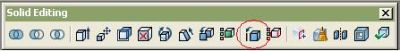
I'm curious - how did you copy the edge of the solid for a path?
From contributor Y:
See image below. Open your Solid Editing toolbar and click on the tool Copy Edges. Then choose the edge you need to copy and that should do it.
From the original questioner:
Awesome! Thanks.
From the original questioner:
Your method worked well. I think the mistake I was making from the beginning was not having my path at the center of the profile. That made all the difference.
From contributor S:
Lofting worked perfect, however I was not able to do this with sweep command. Contributor Y, how did you do it using sweep?

Click here for higher quality, full size image
From contributor Y:
With the "sweep" command, I had to choose a base point for the profile to follow. I used the lower edge of the compound arch after I 3D copied it. It took 4 steps to create half the arch.