Question
I was hoping to get some input as to whether or not my dust collector will be able to handle my needs. I am brand new to woodworking and am setting up in my two car garage and have purchased a Grizzly 1-1/2 hp dust collector with 1300 CFM and 9" static pressure. I want to attach my table saw, 12-1/2 planer, 6-1/8" jointer, 12" band saw, router table, 10" compound miter saw, and small Delta belt sander to the system.
I wanted to run two lines off the dust collector, one of which would go to the tablesaw and planer and another main line to cover the remaining equipment. The longest run in my garage is about sixteen to eighteen feet. I was hoping to run the main line overhead and branch off from there. I wanted to run all four inch flex tubing with appropriate fittings; however, I am not sure if that will be sufficient to handle my equipment. Any input would be greatly appreciated. I was also thinking about using a cyclone separator for larger chips?
Forum Responses
(Dust Collection and Safety Operations Forum)
From contributor D:
The setup you describe should be able to fill your needs, if you run only one machine at a time.
Since you already have a dc, you're limited to working within the capabilities of that particular dc, so let's start there. Typically, these small consumer-model dc's rated to 1200-1300cfm actually deliver roughly 800-860 cfm max airflow with a short length of test-pipe equal in diameter to the blower inlet. This limits the placement of the dc in your shop if you are considering using 6" pipe to any particular machine.
Let's look at your machines for a moment. The largest single requirement machine is your table saw. It would be ideally served with roughly 800 cfm (400 cfm at the base/400 cfm at an over-arm blade-cover). Best to run a 6" pipe from the dc to that saw, and split that 6" main with a 6x4x4 wye. Run one 4" pipe to the base, and the other to your over-arm blade-cover. The dc should be placed relatively close to that saw. Remember, "close" means following the pipe, not a straight line from the dc to the saw. To calculate how far that saw is from the dc, total the length of your straight sections of pipe. Add to that all of the elbows. In terms of resistance, those elbows have to be converted to an "equivalent length" of straight-pipe. A 90 will be equivalent to roughly 12 feet of straight-pipe, and a 45 will be roughly half that amount, or 6 feet. Let's say you have 20 feet of straight-pipe, and two 90's on that run. Well, you'd have an equivalent length of 44 feet. With smooth-walled pipe, you can use a value of roughly .042 per foot of pipe to get your total resistance, which would be 1.85" wc, plus another 1" sp at the hood (entry-loss). Your dc would have to be able to overcome 2.85" sp loss, in order to draw 800 cfm at that saw. That's usually quite easily attainable, if your ducting is efficiently designed. As you can see, following the pipe and converting the elbows adds a lot of length compared to a straight-line measurement from the dc to the saw.
Your planer/jointer may do okay with 4" pipe, but I'd recommend you use 5" pipe and hoods with 5" ports. Expect roughly 500-650 cfm there, if the run is not too restrictive (unnecessary elbows, long runs, etc). 4" pipe should easily serve your other machines.
You can add a pre-separator if you like, but be aware that this will also add its own resistance. In your situation, I'd avoid going with a cyclone separator since your power is limited. You'd lose approximately 4" sp just at the cyclone. I'd recommend a low-resistance drop-box pre-sep. In fact, I'd only use that pre-sep at the planer/jointer. Those machines will produce the largest volumes of waste.
Ceiling-run mains are not a good idea in your situation. That would require up to four 90 degree elbows in your run, along with the straight-pipe (horizontal sections, drop-pipe, and riser from dc to ceiling). The elbows alone may represent 48 feet of equivalent loss. Add to that roughly 36 feet of straight-pipe, and you now have 84 feet of "equivalent length loss". Total resistance for that run would be 3.53"sp, plus the entry-loss. Grand total= 4.53"sp loss. I doubt your dc can deliver that level of performance.
By going with horizontal only ducting (blower-inlet height), you'd eliminate several elbows, plus the up and down pipes (riser/drop). This would effectively shorten your run, plus, horizontal pipe only requires 3500 fpm velocity for effective particle suspension. Even if you were only flowing as little as 685 cfm in that 6" diameter run, you have that 3500 fpm velocity. With ceiling drops, you'd have to be flowing a minimum of 785 cfm for the 4000 fpm velocity those drops require.
One additional note. Your filters will load during use, so add another 1" sp loss there (pressure-drop).
Finally, avoid flex pipe as much as possible. Use it only where it is a must, and keep it as short as possible. Flex-pipe can easily have three times the resistance of smooth-walled pipe.
On the inlet side, you want to make sure that you don't have too much resistance. Choose the appropriate pipe diameter for the desired volume and velocity. 5" pipe, for 475-680 cfm (3500fpm-4000fpm), and 6" pipe for 685-950cfm (3500fpm-4000fpm). Beyond that, use 7" pipe.
If you can squeeze in a pre-separator somewhere along your duct-line, you'll only require proper pipe sizing from the blower to the pre-sep. Since all but the very lightest waste is being dropped there, you can then go with oversized pipe from the pre-sep to the filters. That will reduce the overall resistance, but in order to take full advantage of that, you want to be sure you have free-flowing filters. Having the pre-sep *in* the shop makes it far easier to monitor when it's full.
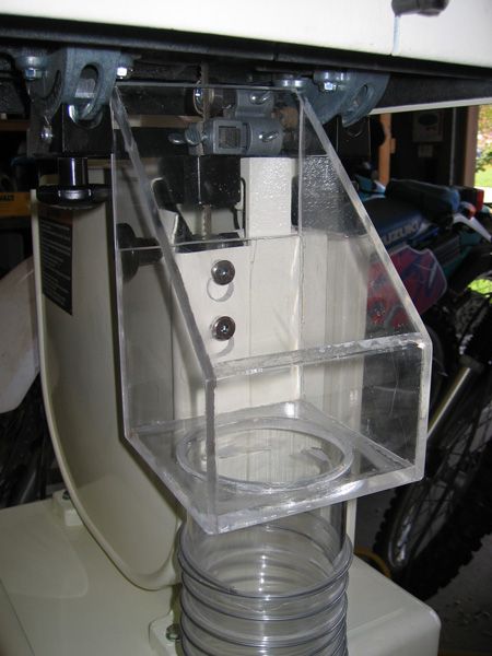
A drop-box can take many forms. It can be a simple drum, with an inlet and outlet in the lid. Sandor's illustration is a box with an inlet on one end, and an outlet directly opposite. In between the two is a knock-down baffle. As waste enters the drop-box, it strikes the baffle, shedding velocity, and drops to the bottom of the box. You can play with pipe diameters to control resistance.
Drop-boxes will not be as efficient as a cyclone when it comes to small-particle pre-separation. That's due to the turbulence within the unit. Basically, you're attempting to remove the bulk of the waste from the air stream. You'll have to play with your porting until you get the desired result.
I'll try to describe an example, for a shop that has no space for a dc. Let's say you have a blower that is ceiling-mounted in a corner of the shop, and that blower is pushing waste. The blower is at one end of the shop, and the only available space for filters is at the opposite end of the shop, or perhaps even outside the shop. The waste doesn't necessarily have to be pushed all the way to that filtration point. You could have a simple pre-sep somewhere along that run, inside the shop. Let's say you're moving 700 cfm. All you'd need is 6" pipe at the blower outlet, to the point directly above, and dropping down to a pre-sep located along that wall. Use a 7' elbow (or larger) and a large diameter pipe to enter the pre-sep. Velocity is not important there, since the waste would simply be dropping down the pipe to the pre-sep. The 6" portion from the blower outlet would be operating at just over 3500 fpm, which is fine for a horizontal run.
For the outlet, use oversized pipe again. You're reducing resistance, and velocity is not important, since you're not supporting waste. The larger, the better. Just run that large diameter pipe back up to the ceiling, and on to your filters. If you don't have large diameter pipe handy, use several smaller diameter pipes. You want that outlet velocity operating below particle suspension levels.
If you were indeed flowing 700 cfm, and you had a 7" pipe for the pre-sep's outlet, velocity in that pipe would be 2621 fpm. With an 8" pipe, that would drop to 2006 fpm. Two 6" pipes would be 1783 fpm, etc.
Think outside the box with pre-seps. That pre-sep may be simply an airtight cabinet with doors, containing a couple of drums, or shop-made waste-boxes with casters. Whatever suits your needs or shop-space.
I'd thought that drop boxes had as much, or more, loss than a cyclone. I've tried to recall what gave me that impression; the best that I can find is Bill Pentz's static pressure calculator. The example shows a trash can separator with a 4.5" loss and a cyclone with a 2.25-4.5" loss depending on its design. I read through all that several years ago, so I'm now guessing that I then *assumed* that a drop-box would have roughly the same pressure loss as a trash can separator.
How much comparative loss could I expect from a drop box such as you've described?
Larger porting can be a problem with such a small interior volume (trashcan). With a 2hp dc and 6" pipe, you'd find that the separator will most likely be "sucked clean". Waste has to shed its velocity before dropping out of the air stream. This is the principle behind cyclone pre-separators. The rotating air mass drives the waste against the interior walls of the cyclone body and cone. Ideally, the cyclone will have enough airflow to keep the waste rotating against the walls of the cone, to a point where the outlet vortex releases the waste at the perimeter of the dust chute. That point of release will vary depending on the amount of air you're pulling. You may have that cyclone hooked up to several machines, with different pipe diameters. That same cyclone may be dealing with 600 cfm at one machine, 800 cfm at another, and 1000 cfm at yet another.
Even with the cyclonic action, you'll find that most well-designed cyclones use a large diameter uptake pipe within the cyclone body. There are two reasons for this. One is to reduce outlet resistance; the other is to ensure that the outlet velocity drops below particle suspension levels. On a cyclone such as the Pentz design, you'll probably find an uptake-tube that is 9" in diameter (1/2 overall diameter,18"). If that cyclone happens to be drawing 800 cfm at a given machine, let's say a saw with a 6" pipe, then the velocity within the 6" pipe will be 4076 fpm. Inside the cyclone body, air will exit at a velocity of 1812 fpm through that 9" pipe. This ensures that only the lowest density waste is sent on to the filters.
The pre-sep I described in the post above uses those principles without cyclonic separation. Of course, you'll have more turbulence with a drop-box than you will with a cyclone. More of the fine waste will find its way to the filters *if* your outlet velocity is high enough to support particle suspension.
In the specific application I described above, we had a blower operating in "push-through" mode. We had 700 cfm flowing at just over 3500 fpm in the 6" blower outlet pipe. At one point, that pipe increases to 7", to drop toward the pre-sep. That diameter could be even larger. Velocity is not important there, as the waste would simply be dropping into the pre-sep. The larger the diameter, the lower the resistance.
At the pre-sep's outlet, we had an 8" pipe. Again, that could be even larger if you want. With 700 cfm in that 8" outlet pipe, velocity is only 2006 fpm. Well below particle suspension levels for all but the lightest waste. That drop-box's resistance would be well under 1/2" sp. (8" plain-end duct at outlet/700cfm.)
Had we used a 6" outlet, that resistance would be 3 times higher, at 1.532"sp. Velocity=3567fpm. Much of the waste could simply blow right on through to the filters.