Z axis oscillation code
Other Versions
Spanish
Programming the Z-axis of a router to use more of the cutting length of the tools. February 19, 2002
Q.
Three people have told me there is a way to program the Z-axis of a router so that it oscillates up and down during a move, thus using more of the cutting length of the tools. Right now I am just shifting the ZO before each new cut. What is the code or concept to program this?
Forum Responses
That depends on the capability of your controller. What material are you cutting that requires this move?
From contributor H:
I would guess that you are cutting a laminated material and you do not want the cutter to wear in one spot. I do not know if there is a specific CNC command, but I do believe that AlphaCam has an option to output the Z moves automatically for this need.
I don't know of a machine code for this. It is available as a feature in the software I use, which writes the Z coordinates to vary up and down the amount of travel you specify as it moves across a tool path. I don't use it because I am cutting on top of a LDF vacuum table.
From contributor K:
Router-CIM includes tool oscillation with all of its profile cutting cycles. Typically, the tool does not move up and down (that increases wear on the Z axis), instead it moves either up or down. You commonly use a fixture for cutting with this operation because to spread out the tool wear, the bottom of the tool would travel deeper than the material thickness. In Router-CIM, you input an oscillation amount as a positive (moves the tool up) or negative (moves the tool down) number. Every line of code will have a Z value ensuring a smooth finish.
From the original questioner:
Contributor K, you wrote "You commonly use a fixture for cutting with this operation because to spread out the tool wear, the bottom of the tool would travel deeper than the material thickness."
Even if you use a fixture, once you make the first cut the tool will still not be cutting any material below the part. In this case I'm not using a fixture - only the vacuum pods. I vary the depth of each different cut so as to use more of the cutting length of the tool instead of wearing it in one 20mm area of the tool.
From contributor K:
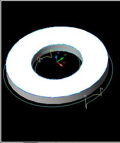
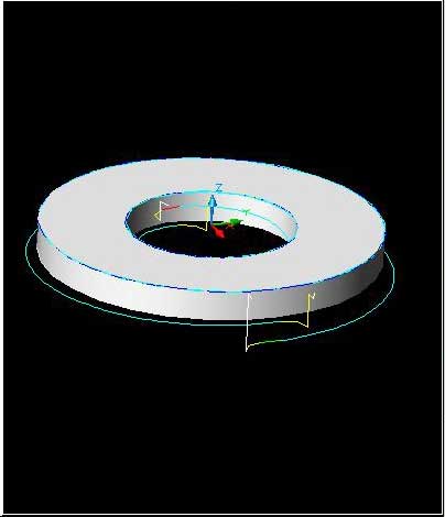
The picture below shows the oscillating tool path. The fixture is only necessary when using a vacuum table with spoil board. In that case, you would be cutting into the spoil board with the oscillating tool path.
From the original questioner:
It appears you are using a Z incremental rather than some type of oscillation up and down in the Z-axis.
From contributor K:
We stopped the up and down motion because the complaint was always that the edge of the part showed the 'witness marks' where the tool went up and down. The constant helix solved the problem, and gave the benefit of additional tool life. Notice the tool path on the outside starts at the full depth, and then travels around the part, ending up 1/2" deeper. That spreads the wear over 1/2" - this works on any shape.
From the original questioner:
"Notice the tool path on the outside starts at the full depth, and then travels around the part, ending up 1/2" deeper."
Yes, I noticed that. That's why I assumed you were using a ZI (ZI12 in your case?).
Contributor K, how did you capture the jpeg image from MD? Did you get the picture by shooting the screen with a digital camera or did you capture the screen with "Snagit" or "Camtasia" type software?
From contributor K:
Just size the window on your desktop, then hold down the ALT key and hit the Print Screen key. This captures your current window. You can also use Control - Print Screen to capture the entire desktop. Then start Windows Paint, and pick Edit, Paste. You can then crop the image, and save as a .jpg or .bmp
What are you cutting that needs this timely execution? Tool wear? The tool is cheap. A code that rides up and down will produce an edge that does the same and exstide your machine time no mater if it's a cool move in Gcode.
From the original questioner:
I have a program that cuts two identical, nested parts from 3/4" particleboard melamine both sides. We are cutting 18,500 L.F. of these parts. I just wanted to use more of the cutting length of the tool rather than just 19.5mm of it.
What is the procedure using Al-Cam 2000?
Al-Cam 2000:
1. Machine/Edit Machining/Edit Z Point by Point.
2. Select Tool Path to modify.
3. Pick either the start or end of the tool path by clicking within the circle that designates the start and end points (appears when you select the tool path initially).
4. Modify the Z value to reflect the oscillation distance.
5. Press esc to exit command.
From contributor H:
After looking at the options, none of them seem that easy for what should be an important controller feature. I am looking at adding this feature directly to the MultiCam controller. I propose to control it from the user interface and a G code command that could have some parameters feed to it. For example:
G?? [Oscillation distance] [Length or Time]
You would call this command and then all of the commands that followed would use the oscillation parameters until a blank G?? was sent. The "oscillation distance" would be added on to the Z axis depth in the file. The cut would begin at the depth that was sent in the file and then would make a continuous Z axis move along the XY cuts starting at the Z axis value and increasing to the additional Oscillation Value. It would be done over a distance or over a time.
I am looking for input or ideas before I write the code.
From the original questioner:
I have not really thought this out, but would some kind of sine or cosine wave work?
From contributor G:
Some controllers have this function, but they force all output to be G01 moves. This means that all the helical arc cuts are point to point and do not accurately represent all geometric entities. That is the primary reason that software controls these types of moves and not controllers via a G code.
From contributor H:
Contributor G, I would do this in the controller so that all of the geometric entities are accurately represented only changing the Z axis moves. It also could be a function that would be associated with a tool #.
From contributor G:
I would think that attaching logic to a tool number would be functionally possible. The Z control as attached to a given tool number would likely be easier than sorting out the geometry (arc or line) would be if you substituted a G code function for the geometric G code. And as a benefit you would not be changing the RS-274D G code standard. You are on the right track!
No one has pointed out that the original questioner is using a Biesse. That oscillation is performed with a Z incremental move. It is a really trick feature of Biesse programming to be able to use absolute values with one axis while using incremental values with another - in the same line of code!
Here is my suggestion: program your PRF in your Work Begin line to just penetrate by .1 mm. Then figure out how much tool length you can use for your oscillation. Divide that by the number of entities in your shape, and put in a ZI (incremental)(positive) on each line so the tool goes a little deeper with each line or arc you program.
I agree that there is no need to go up. What you are trying to do is spread out wear. I don't agree that the tool is cheap enough to ignore the problem. Even if someone gave me a tool, the down time involved in chucking it up, measuring it, replacing it in the machine is all wasted time. I'd rather put in a tool and use it as long as I can. Especially cutting laminated materials, tool life can be more than doubled using oscillation.
I took the point to be tool wear and cycle time was less costly than machine wear.
From the original questioner:
Actually, at least with this program that has two nested parts per panel and 18,500� of routing for this production run, I used a Z-axis origin shift (ZO) before the second, nested part was cut. At the end of the first cut and after the router comes out of the panel, I obviously have an XO YO RT line to prepare for making the next cut. I just added a ZO to get XO YO ZO RT, which makes the second cut deeper, thus spreading the wear over the cutting length of the tool. But I understand what you mean in your example.