HPL Inlay Production Tips
This thread on routing inlay patterns in high-pressure laminate includes a good lesson about Cutter Radius Compensation, which lets the operator make allowances for tool wear without re-coding the program. October 3, 2011
Question
I have a job making a table top with HPL, and the customer's logo will be an inlay with a different color. I have done very little CNC routing with HPL laminate. What would the best type of router bit be for my vac table? Shoda router. Any general suggestions about routing and working with HPL?
Forum Responses
(CNC Forum)
From contributor J:
I have done this with my CNC with excellent results. Vectric software has an inlay toolpath function in both Aspire and Vcarve Pro for 2D direct inlay work. A small amount of practice can make anyone an expert at it. Look for the video at vectric.com under training materials, vcarvepro, 2d/2.5d videos. There is one for autoinlay.
From contributor S:
I have used the Vectric software to make HPL inlays. It works very well but you will have to do a little trial and error to get it nailed in. You may have to play with the offset to get it to fit perfect. But that function is there.
From the original questioner:
Thanks. I use Router-CIM software. What Onsrud router bit would be best?
From contributor J:
I use a .125 ds depending on the size of the inlay.
From contributor T:
With Router-CIM I'd use about a .010" offset for fit. The cutter geometry I'd start with is a straight profile, with a slow down spiral to prevent chipping. A V flute is going to be the strongest edge and the most cutter life. (That might be a tough combination to find; if so, try no spiral.) And of course the diameter matched to your smallest inside radius. You can use CRC (Cutter Radius Compensation) to tighten up or loosen up the fit. RouterCIM fully supports CRC. Unfortunately Vetric does not.
From contributor J:
Contributor T, when you refer to CRC (cutter radius compensation) you are referring to an offset because of varied tool thickness? Isn't this the function of the allowance offset in Aspire's inlay toolpathing?
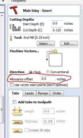
Click here for higher quality, full size image
From contributor V:
What type of shape are you trying to inlay?
I have done some simple inlays in p lam by just using 1/4" downsheer bit. You just have to zero your bit in perfect and make your corners at least the radius of your bit. And change your G41 to G42. Yes, the Vetric software would be the best way to do it, but if you only have a simple one to do, you can make it work without it.
From contributor J:
Here is one we helped a fellow woodwebber with last year.

Click here for higher quality, full size image
From contributor T:
CRC (Cutter Radius Compensation) is a higher level machine control function using G40, G41, and G42. CRC allows the machine operator to adjust the tolerances without making a new program.
Of course, as you suggest, you can always write a unique program every time you sharpen a bit or want to tweak a fit tolerance, but it's not always the best use of time.
Router-CIM's logic interrogates the drawing and determines if a G41 (Comp Left) or G42 (Comp Right) is best to use and inserts the coding. Then at the machine side, the sharpening amount of the tool, or fit allowance, can be adjusted on the fly. For example in fitting HPL segments together, let�s say you allowed .004� and wanted to open it up a little more. Simply click the value to edit the CRC amount, and rerun the program. Total editing time less than 5 seconds.
You may not be familiar with this function because your machine uses a less intuitive software, as the more recent, graphic based, operating systems. Here's a picture that shows how quickly CRC values can be edited on the NEW CNC machines operating system.
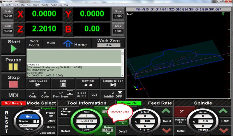
Click here for higher quality, full size image
From contributor J:
It does not matter at the controller (mach3 or wincnc), as if the correct diameter is not entered at the toolbase info before file production, then it is moot. Why oversell or overtech this? To do the same process may take 6 seconds. I thought there was something special to this CRC thing. Still not enough for me to consider mach 3.
From contributor T:
You have missed the point entirely. Let�s presume that the definitions in the tool tables in your CAM software are set up to the tool diameter of a new, never been sharpened, cutter. That is to say a 1/4" router bit has a .250" diameter. So any part program you write uses those tool diameter settings.
Next, let�s say the tools you mounted in your machine are a combination of sharpened ones and new ones. My point is that good operating software will allow machine level variables, like actual tool diameters, to be compensated for, on the fly, at the machine side, and not require a new part program. All programs are written using "new tool" diameters, and any variation is recorded on the CNC control.
Your way, while valid, means that you will need to enter an allowance offset in your CAM software for each re-sharpened tool, and then create a unique tool path, for that part using those exact tools. That program will only work for that specific combination of tool diameters. So if you are using a 4 tool part program, there could be lots and lots of versions of the same program.
For the case in point, it would be a simple matter to change the fit tolerance of HPL segments at the machine. You would not need to walk back to the office, power up the PC that has the CAM software, fire up the software, open up the part file, edit the appropriate tool paths, save the new settings, repost the program, send the program to the machine, enable the new program, and run it. That sounds like it could take a little more than 6 seconds to me.
From contributor J:
That was an excellent explanation and I appreciate it. With wincnc, my cam and controller are on the same computer, and while I design all over the place (I have a few computers here and there), I always cam at the machine. I have never needed this, as wincnc and Vectric or any software can run autonomous of each other while the machine is operating. Wincnc does allow for this. I have just never used it as my current machine is an x3 multihead so I set all at once and go. I have ordered a new ATC so this may be something I am about to learn.
From contributor G:
I have a feature on my machine that allows for a difference in the cam program and the difference at the controller. Where you would get the tool sharpened and it lost size, the controller would then compensate for the tool correction so the cam program would not have to be altered, if that makes sense.