Don Jones has spent the past 20 years using and customizing AutoCAD in the stair manufacturing industry.
This article presents the basics on producing G-code using nothing but AutoCAD and one of its built-in programming languages. The programming language used is AutoLISP, but the article assumes the reader knows nothing about AutoLISP (this could also be done with VBA or VSTA). It is assumed, however, that the reader does know AutoCAD and G-code.
Contents:
CHAPTER 1 - SOME LISP BASICS
CHAPTER 2 - CREATING G-CODE (G0)
CHAPTER 3 - MORE G-CODE (LINEAR MOVES)
CHAPTER 4 - ARCS (G2 AND G3)
CHAPTER 5 � STANDARD BLOCKS OF G-CODE
CHAPTER 6 � AUTOMATE THE PROCESS
CHAPTER 7 � AUTOMATE THE DRAWING
CHAPTER 8 � G-CODE TO DRAWING
�
USING AUTOCAD AND AUTOLISP
�
The author makes no express or implied warranty of any kind and assumes no responsibility for errors or omissions.� No liability is assumed for incidental or consequential damages in connection with or arising out of the use of the information or programs contained herein.
�
AutoCAD and AutoLISP are registered trademarks of Autodesk, Inc.
�
�
There are many reasons why one might want to create his own programs to generate CNC code from tool paths drawn in AutoCAD.� Perhaps you can not find a commercial program that does exactly what you want it to do, what your needs are don�t warrant the cost of a commercial program, you want more control of the CNC code, or you may just enjoy the challenge of doing it.� This book will show you the basic principles to get you started.� From there, you can add as many bells and whistles as you desire.
�
The last chapter, G-CODE TO DRAWING, will show you how to reverse the process and generate a drawing of the tool path from the CNC code.� Many commercial programs will simulate the operation of the machine, but do not use the CNC code to do it.� Instead, they use the same tool path drawing that was used to generate the CNC code.� If the code is then manually edited, the simulation will not be accurate.
�
This is not a course on AutoLISP.� There are plenty of good books on the market that do that.� However, I will explain those things that you need to know about AutoLISP in order to accomplish what we are trying to do.� If you already know AutoLISP, you may find my explanations a little simplistic, but I am trying to keep it as simple as I can for those that don�t, so please bear with me.
�
We are going to start out with some AutoLISP basics.� From here on I will refer to AutoLISP as just LISP.
�
LISP is built into AutoCAD; there is nothing extra to buy.� A LISP program is a Plain Text .txt file, except that the file extension of the file name has to be .lsp in place of .txt.� Any text editor that can save files as Plain Text can be used to create LISP programs.� I like to use Microsoft WordPad.
�
VisualLISP is also built into AutoCAD.� VisualLISP is essentially a special text editor used to create and test LISP programs.� It has a lot of neat features to make it easier to create and test programs, so you may want to check it out. �You can, however, get by just using a plain old text editor.
�
BASIC STRUCTURE OF LISP PROGRAMS
�
Here is a LISP program:
�
(DEFUN C:TEST( )
��� ;This is a demonstration
��� (SETQ PT (GETPOINT �Pick a point on the screen:�))
��� (COMMAND �TEXT� PT �1� �� �HELLO WORLD� ��)
)
�
LISP programs consist of parentheses nested inside of parentheses.� Every program begins with an open parenthesis and ends with a close parenthesis. �Every program also begins with DEFUN which stands for DEFine FUNction.� After DEFUN comes the name of the function.� If you put C: in front of the name, that name becomes a Command Line command.� If this program were loaded into a drawing, you could type TEST at the Command Line and the program would run.� So, what we have talked about so far is this:
�
(DEFUN C:TEST( )
�
�
�
)
�
You can ignore the set of parentheses at the end of TEST for now.
�
The next line down is �;This is a demonstration�.
�
(DEFUN C:TEST( )
��� ;This is a demonstration
�
�
)
�
Anything with a semicolon in front of it is ignored.� You use this to make notes to yourself, or comments, inside the program.� Notice the indentation.� Indentations do not matter to the program and just make things easier for people to read.� The indentations help to see how things are nested.� Blank lines also do not matter to the program.� You can place blank lines in the program to separate parts that do different things.� Again, this is just to make it easier to read.
�
The next line is a set of nested parentheses.
�
(DEFUN C:TEST( )
��� ;This is a demonstration
��� (SETQ PT (GETPOINT �Pick a point on the screen:�))
�
)
�
We will look at the inside set first which is:
�
������������ (GETPOINT �Pick a point on the screen:�)
�
GETPOINT is a LISP command that gets the X, Y, and Z values of a point that the user picks on the drawing.� (GETPOINT) with just the parentheses before and after the command will do that, but will not prompt you.� It also has an option for a prompt that will appear on the Command Line.� That is what �Pick a point on the screen:� is.
�
The outside set of parentheses is (SETQ PT���������������������������������������� ).� SETQ is a LISP command that stores a piece of information as a name.� The name is called a variable.� You make up the name that you want to use.� For example, (SETQ MYTXT �Ralph�) will store the text �Ralph� as the variable MYTXT.� If I then tell it to print out MYTXT, it will print �Ralph.�� Now look at the entire line.
�
��� (SETQ PT (GETPOINT �Pick a point on the screen:�))
�
GETPOINT gets a point that is picked on the screen.� SETQ stores that point as the variable PT.
�
Just as comments, indentations and blank lines can be used to make a program easier to read, you also do not have to put everything on one line.� You could also write this line like this:
�
��� (SETQ PT
���� ���(GETPOINT �Pick a point on the screen:�)
��� )
�
The next line is (COMMAND �TEXT� PT �1� �� �HELLO WORLD� ��).� COMMAND will send text to the AutoCAD Command Line as though it were typed in.� The first item following COMMAND is �TEXT.�� This is the same as typing the AutoCAD command TEXT at the Command Line.� When you start the TEXT command you are first asked to pick a start point for the text.� The variable PT has a point stored in it and that point is fed to the TEXT command.� The next thing asked for by the TEXT command is the text height.� The �1� gives it a text height of 1.� Next the rotation angle is asked for with a default of 0.� A set of empty quotes with no space between them is the same as hitting the ENTER key, which accepts the default.� The next thing asked for is the text.� That is �HELLO WORLD�.� After the text is entered, the next line of text is asked for and again an empty set of quotes is used for ENTER which ends the TEXT command.
�
Put it all together and you have:
�
(DEFUN C:TEST( )
��� ;This is a demonstration
��� (SETQ PT (GETPOINT �Pick a point on the screen:�))
��� (COMMAND �TEXT� PT �1� �� �HELLO WORLD� ��)
)
�
LOADING AND RUNNING LISP PROGRAMS
�
There are a number of ways to load a LISP program into AutoCAD.� One way is to go to Tools, Load Application, then browse for the file and load it from there.� Another way is to load it using the Command Line.� Let�s say that our program is stored on the root of the C drive.� To load it using the Command Line you would type (load �c:/demo�).� Note that in the path you use forward slashes in place of back slashes.� You can also load it from a custom menu or button. �Use the same text for the menu macro as you would type at the command line.� To both load and run the program from a custom menu or button use (load �c:/demo�);test for the macro.
�
You can have more than one function in a LISP file.� For example, in our Demo.lsp file we might have:
�
(DEFUN C:TEST1( )
��� ;This is a demonstration
��� (SETQ PT (GETPOINT �Pick a point on the screen:�))
��� (COMMAND �TEXT� PT �1� �� �HELLO WORLD� ��)
)
�
(DEFUN C:TEST2( )
�� �;This is a demonstration
��� (SETQ PT (GETPOINT �Pick a point on the screen:�))
��� (COMMAND �TEXT� PT �1� �� �GOODBY WORLD� ��)
)
�
Now, if you load Demo.lsp and type TEST1 you will get HELLO WORLD and if you type TEST2 you will get GOODBY WORLD.
�
You could have two custom buttons, or two custom menu items, called TEST1 and TEST2 with the macro for TEST1 being (load �c:/demo�);test1 and the macro for TEST2 being (load �c:/demo�);test2.� If you click on the TEST1 button it will load Demo.lsp, run TEST1, and you will get HELLO WORLD.� If you then click on the TEST2 button it will re-load Demo.lsp, run TEST2, and you will get GOODBY WORLD.� The TEST2 button would not have needed to re-load Demo.lsp because it was already loaded by TEST1, but it would not have been if you clicked on TEST2 first, and it doesn�t hurt anything to re-load the file.
�
There are just two more things that I would like to mention in this section.� One is that you can type LISP commands into the Command Line.� If you type (SETQ PT (GETPOINT �Pick a point on the screen:�)) at the Command Line, you will be prompted to pick a point on the screen, and when you do, that point will be stored as the variable PT.
�
The second thing is that you can find out the value of variables by typing an exclamation point and the variable name at the Command Line.� If you type !PT you will see the X, Y, and Z values of the point that you picked.
�
CHAPTER 2 - CREATING G-CODE (G0)
�
Let�s say that our LISP program file is called CNC.LSP and is in the directory is C:\CADCAM\.� In that file we will place several functions and create a custom menu item or custom button for each function.
�
WORKING WITH FILES
�
Your CNC programs are text files, so we need to be able to either create new files or add to existing files.� The first thing that we need to do is get the name of the path and file name of the existing file or the new file to create.� The LISP command we use to do that is GETFILED.� This command will bring up a file browsing window that you can use to find an existing file or name a new one.� We will look at getting the path and name of a new file first.
�
Let�s say that the directory that our CNC programs are saved in is C:\CNCPROGRAMS.� To retrieve the path and file name of an existing file we could write something like this:
�
(GETFILED �� �� �� 1)
�
Notice that there are three sets of empty quotes.� The first is for a Title option which places a title in the Title Bar of the file browsing window.� If left empty, the title will be �Create File.�� Since we are creating a new CNC program file we might do something like this: (GETFILED �Enter New CNC Program File Name�� �� �� 1).
�
The next set of quotes is an option for a default directory path for the file browser to start in.� We might always want it to start out in C:\CNC\, so it would be (GETFILED �Enter New CNC Program File Name�� �C:/CNCPROGRAMS/� �� 1).� Note the forward slashes.
�
The last set of quotes is for a file extension option.� If our CNC program files ended with the file extension .txt, then (GETFILED �Enter New CNC Program File Name�� �C:/CNCPROGRAMS/� �TXT� 1) would have the file browser show only files that end with .txt.� If left empty, all files are displayed.
�
After the three quoted options is a number that can be a 1 or 0.� In our example a 1 is used.� That tells the file browser that you want to create a new file.� If you pick on an existing file or type in the name of an existing file, the message �The file already exists.� Do you want to replace it?� will appear.� A 0 will tell the file browser that you are looking for an existing file.� In that case, if you type in the name of a nonexistent file, the message �File does not exist.� will appear.
�
We will call our first function NEWFILE.� The title for our file browser will be �Enter New CNC Program File Name�, the default directory will be �C:/CNCPROGRAMS/� and the file browser will show all file extensions.� Here is the start of our function.
�
(DEFUN C:NEWFILE( )
��� (GETFILED �Enter New CNC Program File Name�� �C:/CNCPROGRAMS/� �� 1)
)
�
As I said before, GETFILED gives us a path and file name.� We need to store that as a variable.
�
(DEFUN C:NEWFILE( )
� ��(SETQ FILE (GETFILED �Enter New CNC Program File Name� �C:/CNCPROGRAMS/� �� 1))
)
�
Now to actually create the file.� To do that we use the LISP command OPEN as follows:
�
������������ (OPEN FILE �w�)
�
Of course, FILE is our variable for the path and file name.� The �w� tells the OPEN command to open the file in the write mode.� If no file by that name exists, a new file will be created.� If the file already exists, then it will be replaced by the new one.� With �a� the file will be opened in the append mode and any new information will be added on to the end of the existing file.� An �r� will open the file in the read only mode.� The OPEN command not only opens a file, but it also provides a reference to it so that you can refer to that file to do things to it.� That reference, or file pointer, needs to be stored as a variable.
�
In the NEWFILE function, use the OPEN command, the variable FILE, and the �w� option to open a new file.� Store the file pointer that the OPEN command provides, as the variable FP.
�
(DEFUN C:NEWFILE( )
� ��(SETQ FILE (GETFILED �Enter New CNC Program File Name�� �C:/CNCPROGRAMS/� �� 1))
� ��(SETQ FP (OPEN FILE �w�))
)
�
We may want to add to an existing file instead of creating a new one.� Add the following function.
�
(DEFUN C:ADDTOFILE( )
� ��(SETQ FILE (GETFILED �Select Existing CNC Program�� �C:/CNCPROGRAMS/� �� 0) )
� ��(SETQ FP (OPEN FILE �a�))
)
�
We are now ready to write something to the file that we just opened.� We will do that in a separate function called G0.� The LISP command to do that is WRITE-LINE.
�
� ��(WRITE-LINE �G0 X0.0 Y0.0 Z0.0� FP)
�
The structure for this command is (WRITE-LINE [text] [file to write to] ).
�
(DEFUN C:G0( )
� ��(WRITE-LINE �G0 X0.0 Y0.0 Z0.0� FP)
)
�
We just created a line of G-code.� Not very useful G-code, but it�s a start.� Once we are done writing information to a file we need to close it.� That also will be done in a separate function called CLOSEFILE using the CLOSE command.
�
(DEFUN C:CLOSEFILE( )
� ��(CLOSE FP)
)
�
Here is what the LISP file C:\CADCAM\CNC.LSP looks like so far:
�
(DEFUN C:NEWFILE( )
� ��(SETQ FILE (GETFILED �Enter New CNC Program File Name�� �C:/CNCPROGRAMS/� �� 1))
� ��(SETQ FP (OPEN FILE �w�))
)
�
�(DEFUN C:ADDTOFILE( )
� ��(SETQ FILE (GETFILED �Select Existing CNC Program�� �C:/CNCPROGRAMS/� �� 0))
� ��(SETQ FP (OPEN FILE �a�))
)
�
(DEFUN C:G0( )
� ��(WRITE-LINE �G0 X0.0 Y0.0 Z0.0� FP)
)
�
(DEFUN C:CLOSEFILE( )
� ��(CLOSE FP)
)
�
ENTERING TEXT AT THE COMMAND LINE
�
You don�t always want to G0 to X0.0 Y0.0 Z0.0.� One thing that you might want to do would be to manually type in a line of G-code. �We will create a function to do that and call it TXT.
�
(DEFUN C:TXT( )
��� (SETQ MYTEXT (GETSTRING T �Enter text: �)
��� (WRITE-LINE MYTEXT FP)
)
�
The LISP command GETSTRING will allow for text to be typed in at the Command Line.� The structure for this command is (GETSTRING [cr] [prompt] ).� Prompt and cr are optional.� If the cr option is left out, the text can have no spaces in it.� Hitting the space bar is the same as hitting ENTER.� If anything is provided in the cr spot, for example T, then spaces can be used.� The prompt option provides a prompt at the Command Line.
�
GETTING POINTS FROM AUTOCAD
�
We have already seen how to get a point from AutoCAD with the GETPOINT command.� Now we will get a little more detailed.
�
Set the osnap to endpoint
�
You can set the OSNAP to Endpoint either by the Command Line or by setting the system variable.� To use the Command Line:
�
� ��(COMMAND �OSNAP� �ENDP�)
�
To use the system variable:
�
�� �(SETVAR �OSMODE� 1)
�
The value 1 is for Endpoint.� If you want to set the OSNAP to Midpoint, you would set OSMODE to 2, use 4 for Center, 16 for Quad, 32 for Intersection, 512 for Nearest, and 0 is for None.
�
You may want to save the current OSNAP setting before changing it so that you can put it back to its previous setting.� You do that by saving the value of the system variable:
�
� (SETQ OLDSNAP (GETVAR �OSMODE�))
�
After changing the OSNAP setting, you can then restore the original setting:
�
� ��(SETVAR �OSMODE� OLDSNAP)
�
Pick the end point of the line
�
After the OSNAP is set to Endpoint, you are ready to pick the end point of a line or arc.
�
� ��(SETQ PT (GETPOINT �Select end point:�))
�
The GETPOINT command allows for an optional prompt that will appear on the Command Line.� In this case �Select end point:� is the prompt.
�
Let�s say that for the point picked the X value is 12.34, the Y value is 15.625 and the Z value is 0.0.� The value of PT will look like this:
�
(12.34 15.625 0.0)
�
Data contained inside parentheses is called a list.� In fact, LISP stands for List Processing.
�
Extract the X, Y, and Z values of the point
�
The X value is 12.34, the Y value is 15.625 and the Z value is 0.0.� You can extract the individual values as follows:
�
� ��(SETQ XVALUE (CAR PT))
� ��(SETQ YVALUE (CADR PT))
� ��(SETQ ZVALUE (CADDR PT))
�
CAR gives you the first item in a list.� CDR gives you a list of everything in a list, except the first item.� You use combinations of CAR and CDR to get the item that you want from a list.� (CADR PT) is the equivalent of (CAR (CDR PT)).� If PT is (12.34 15.625 0.0), then (CDR PT) will give you (15.625 0.0) and (CAR (CDR PT)) will give you 0.0.
�
You may, or may not, need ZVALUE, but we will go ahead and get it and decide later if we want to use it.
�
CREATE THE LINE OF G-CODE
�
The values of XVALUE, YVALUE, and ZVALUE are numbers (real).� You need them to be text (strings) to combine them with other text in order to create the G-code commands.� The following will convert the values to strings and save those strings as the variables XSTRING, YSTRING, and ZSTRING.
�
� ��(SETQ XSTRING (RTOS XVALUE 2 4))
� ��(SETQ YSTRING (RTOS YVALUE 2 4))
� ��(SETQ ZSTRING (RTOS ZVALUE 2 4))
�
The command RTOS stands for Real TO String.� Note the two numbers, 2 and 4.� The first number determines the Units format.� Architectural is 1, Decimal is 2, Engineering is 3, Fractional is 4, and Scientific is 5.� We are using 2 for Decimal.� When the Units are set to Decimal the next number in the RTOS command sets the number of places to the right of the decimal point, in this case 4.� The value of XSTRING is now the text �12.3400�, YSTRING is �15.6250�, and ZSTRING is �0.0�.
�
G-code requires an X in front of the X value, a Y in front of the Y value, and a Z in front of the Z value.� Use the STRCAT command to put text together.
�
� ��(SETQ CNCX (STRCAT �X� XSTRING))
� ��(SETQ CNCY (STRCAT �Y� YSTRING))
� ��(SETQ CNCZ (STRCAT �Z� ZSTRING))
�
The value of CNCX is the text �X12.3400�, the value of CNCY is the text �Y15.6250�, and the value of CNCZ is the text �Z0.0�.� All you need now is the G-code command.
�
� ��(SETQ TXT (STRCAT �G0 � �CNCX �� � �CNCY))
�
Note that a space is included at the end of G0 and between CNCX and CNCY. The value of TXT is the text �G0 X12.3400 Y15.6250�.� �For now, we will not use CNCZ.
�
If you want to, you can shorten things up by combining steps.
�
� ��(SETQ TXT (STRCAT �G0 X� (RTOS XVALUE 2 4) � Y� (RTOS YVALUE 2 4)))
�
This will add together the text �G0� SPACE �X�, the text from (RTOS XVALUE 2 4), the text SPACE �Y�, and the text from (RTOS YVALUE 2 4) to give you the text �G0 X12.3400 Y15.6250�.
�
WRITE THE LINE OF G-CODE OUT TO THE FILE
�
Writing the line of text out to the file is simple.� Remember that structure for WRITE-LINE is (WRITE-LINE [text] [file to write to] ).
�
� ��(WRITE-LINE TXT FP)
�
Just so we know what line of G-code we just created, let�s also print it out on the Command Line.
�
� ��(PROMPT TXT)
�
If you do this you will discover a slight problem.� The line of G-code will be added to the end of the previous text on the Command Line and you will get something like:
�
Select end point:G0 X12.34 Y15.625
�
We need to add a control character, in this case a new line character, to the front of our string.� The new line control character is �\n�.� The case is important here, it must be a small �n�.
�
� ��(PROMPT (STRCAT �\n� TXT))
�
Here is what we have for the G0 function so far.
�
(DEFUN C:G0( )
� ��;Save OSNAP setting and set OSNAP to Endpoint
� ��(SETQ OLDSNAP (GETVAR �OSMODE�)
� ��(SETVAR �OSMODE� 1)
�
� ��;Pick the Endpoint of the line
� ��(SETQ PT (GETPOINT �Select end point:�))
��� ;Extract the point values
��� (SETQ XVALUE (CAR PT))
��� (SETQ YVALUE (CADR PT))
��� (SETQ ZVALUE (CADDR PT))
�
��� ;Change values to text
��� (SETQ XSTRING (RTOS XVALUE 2 4))
��� (SETQ YSTRING (RTOS YVALUE 2 4))
��� (SETQ ZSTRING (RTOS ZVALUE 2 4))
�
��� ;Create text for G-code command
��� (SETQ CNCX (STRCAT �X� XSTRING))
��� (SETQ CNCY (STRCAT �Y� YSTRING))
��� (SETQ CNCZ (STRCAT �Z� ZSTRING))
�
��� (SETQ TXT (STRCAT �G0 � CNCX � � CNCY))
�
� ��;Write text out to file
� ��(WRITE-LINE TXT FP)
�
� ��;Write text to Command Line
� ��(PROMPT (STRCAT �\n� TXT))
�
� ��;Set OSNAP back to original value
� ��(SETVAR �OSMODE� OLDSNAP)
);Defun C:G0
�
RELATIVE COORDINATES
�
The G-code that we just created uses absolute coordinates.� You can also use relative coordinates.� In order to do that you need to store the last X, Y, and Z values used.� You could store them as LASTX, LASTY, and LASTZ.� These variables could be set to 0 to start.� The last value is subtracted from the current value and that will give you the relative value.� The following shows how to do this by adding additional LISP statements.� The additional statements are in bold.
�
��� ;Extract the point values
��� (SETQ XVALUE (CAR PT))
��� (SETQ YVALUE (CADR PT))
��� (SETQ ZVALUE (CADDR PT))
�
��� (SETQ THISX XVALUE)
��� (SETQ THISY YVALUE)
��� (SETQ THISZ ZVALUE)
�
��� (SETQ XVALUE (- THISX LASTX))
��� (SETQ YVALUE (- THISY LASTY)
��� (XETQ ZVALUE (- THISZ LASTZ)
�
��� ;Change values to text
��� (SETQ XSTRING (RTOS XVALUE 2 4))
��� (SETQ YSTRING (RTOS YVALUE 2 4))
��� (SETQ ZSTRING (RTOS ZVALUE 2 4))
�
���� ;Create text for G-code command
��� (SETQ CNCX (STRCAT �X� XSTRING))
��� (SETQ CNCY (STRCAT �Y� YSTRING))
��� (SETQ CNCZ (STRCAT �Z� ZSTRING))
�
��� (SETQ TXT (STRCAT �G0 � CNCX � � CNCY))
�
��� (SETQ LASTX THISX)
��� (SETQ LASTY THISY)
��� (SETQ LASTZ THISZ)
�
CHECK FOR OBJECT AT POINT
�
If you have the Osnap set to Endpoint and you pick on the screen where there is no object, you will get the point where you picked.� You will not get an error message saying that there is no object at that point.� That is a hazard that needs to be avoided and we can add something to our program to do that.� We can test to see if there is an object at that point.� When you select objects in AutoCAD you are creating a selection set.� You can also do that in LISP with SSGET.� When you select objects you can use a single point, a crossing, a window, previous, last, and so on.� You can also do that with SSGET.� You also need to save the selection set to a variable.� The following uses SSGET and a crossing.� The two points for the crossing will be the same point, PT, that was just picked.� When having LISP pick something at a point, it is best to use a crossing window and the same point twice because selecting with just a single point could grab the wrong object, depending on the size of the pick box.
�
� ��(SETQ SS (SSGET �C� PT PT))
�
If no objects are found at that point, the value of SS will be NIL.� In LISP speak NIL means no value at all.� We can check to see if SS is NIL using the LISP command IF.� The structure of the IF command is this:
�
(IF [some condition] [do this] [else, do this instead] )
�
The (else, do this instead) is optional.� You could write an IF statement that looks like this:
�
� ��(IF (= SS NIL) (PROMPT �No object detected at that point!�))
�
This will print out �No object detected at that point!� on the Command Line if SS is equal to NIL.� Notice that the equal mark is first and not between SS and NIL.� Any math function always comes first.� If you wanted to add the variables A and B it would be (+ A B).� In place of PROMPT you might want to use the LISP command ALERT.� This will place the message in a message box instead of on the Command Line.
�
If we put this in our LISP program right after the point is picked, it would detect that we missed picking an end point and tell us so; but the rest of the program would then continue, using the values of the point that was picked.� If SS is equal to NIL we also need to pick another point.� We could do that by adding another IF statement.
�
��� (IF (= SS NIL) (SETQ PT (GETPOINT �Select end point:�)))
�
A better way to do this would be to put both the error prompt and picking the new point in one IF statement, but you can only have one set of parentheses there.� A second set would be the Else part of the IF statement.� There is a way to get around this by using the PROGN command.� The LISP command PROGN will take several LISP commands and group them together so that the group can be used where only one command is expected.� This is how you could do it.
�
������(IF (= SS NIL)
�������� (PROGN
����� �������(ALERT "No object detected at that point!")
������������ ;Pick the Endpoint of the line
������������ (SETQ PT (GETPOINT "\nSelect end point:"))
�������� )
��� �)
�
Here is what we have so far for the G0 function
�
(DEFUN C:G0( )
� ��;Save OSNAP setting and set OSNAP to Endpoint
� ��(SETQ OLDSNAP (GETVAR �OSMODE�))
� ��(SETVAR �OSMODE� 1)
�
� ��;Pick the Endpoint of the line
� ��(SETQ PT (GETPOINT �Select end point:�))
�
� ��;Test for object at that point
��� (SETQ SS (SSGET �C� PT PT))
��� �(IF (= SS NIL)
�������� (PROGN
����� �������(ALERT "No object detected at that point!")
������������ ;Pick the Endpoint of the line
������������ (SETQ PT (GETPOINT "Select end point:"))
�������� )
��� �)
�
��� �;Extract the point values
���� (SETQ XVALUE (CAR PT))
��� �(SETQ YVALUE (CADR PT))
��� �(SETQ ZVALUE (CADDR PT))
�
��� �;Change values to text
���� (SETQ XSTRING (RTOS XVALUE 2 4))
��� �(SETQ YSTRING (RTOS YVALUE 2 4))
� ���(SETQ ZSTRING (RTOS ZVALUE 2 4))
�
�� ��;Create text for G-code command
���� (SETQ CNCX (STRCAT �X� XSTRING))
� ���(SETQ CNCY (STRCAT �Y� YSTRING))
��� �(SETQ CNCZ (STRCAT �Z� ZSTRING))
�
��� �(SETQ TXT (STRCAT �G0 � CNCX � � CNCY))
�
�� ��;Write text out to file
� ���(WRITE-LINE TXT FP)
�
��� �;Write text to Command Line
��� �(PROMPT (STRCAT �\n� TXT))
�
��� ;Set OSNAP back to original value
�� �(SETVAR �OSMODE� OLDSNAP)
) ;Defun C:G0
�
CYCLE IF NO OBJECT IS FOUND
�
The way the G0 function is written so far, if no object is found at the picked point, an error message is given and you are given another chance to pick the point.� If you miss the end point the second time, the rest of the program will then continue, using the values of the point that was picked.� What might be better would be if the program would keep asking you to try again until you pick the correct point or until you give up by hitting ESC.� To do this we can use the WHILE command.� The structure for the WHILE command is (WHILE [some condition] [do any number of things] ).� We are going to use two conditions for our WHILE command, SS is equal to NIL (= SS NIL) and PT is not equal to NIL (/= PT NIL).� The value that you get with GETPOINT, if you hit ENTER instead of picking a point, is NIL.� These two conditions are combined with the LISP command AND.
�
We want the WHILE loop to cycle through at least once, so we need to make sure that SS is equal to NIL to start with.� We will put picking the point and testing for an object inside the While loop.� When the program runs, SS is first set to NIL and we go through the loop.� If we pick an endpoint SS will not be NIL, so we will not go through the loop again.� If we pick on an empty spot SS will be NIL, we will get the error message, and we will go through the loop again, being asked to pick an end point.� This will continue until SS is no longer equal to NIL or we hit ESC.� There is only one small problem.� Each time we go through the loop �Select end point:� is tacked on to the previous �Select end point:�.� We need to add a line feed control character to the front of �Select end point:� like so:
�
��������������� (SETQ PT (GETPOINT �\nSelect end point:�))
�
With these things added, this is what we have:
�
��� (SETQ SS NIL)
�� �(WHILE (AND (= SS NIL)(/= PT NIL))
������� (SETQ SS (SSGET "C" PT PT))
������ �(IF (AND (= SS NIL)(/= PT NIL))
���������� �(PROGN
��������������� (ALERT "No object detected at that point!")
����������� ����;Pick the Endpoint of the line
��������������� (SETQ PT (GETPOINT "\nSelect end point:"))
����������� );Progn
������� );If
�� �);While
�
The While statement will loop as long as SS is equal to nil (no object at that point) and PT is not equal to nil (a point is picked).� If you hit ESC when asked to pick a point, PT will equal NIL and you will drop out of the WHILE statement.� The problem there is that the rest of the program will try to continue with no value for PT and it will error out.� To solve that problem we need to put the rest of the program inside an IF statement.� Again, we need the PROGN statement.
�
�� ��(IF (/= PT NIL)
����� ��(PROGN
������� ����;Extract the point values
������� ����(SETQ XVALUE (CAR PT))
������� ����(SETQ YVALUE (CADR PT))
������� ����(SETQ ZVALUE (CADR PT))
�
������� ����;Change values to text
������� ����(SETQ XSTRING (RTOS XVALUE 2 4))
������� ����(SETQ YSTRING (RTOS YVALUE 2 4))
������� ����(SETQ ZSTRING (RTOS ZVALUE 2 4))
�
������� ����;Create text for G-code command
������� ����(SETQ CNCX (STRCAT �X� XSTRING))
������� ����(SETQ CNCY (STRCAT �Y� YSTRING))
������� ����(SETQ CNCZ (STRCAT �Z� ZSTRING))
������� ����(SETQ TXT (STRCAT �G0 � CNCX � � CNCY))
�
������� ����;Write text out to file
������� ����(WRITE-LINE TXT FP)
�
������� ����;Write text to Command Line
������� ����(PROMPT (STRCAT �\n� TXT))
����� ��);Progn
�� �);If
�
USE Z VALUE
�
There is one more thing that we could add to our G0 function, and that is optional.� You might want to have the
Z value of the point picked included in the line of G-code.� Even if you do, it is something that you probably would want to be able to turn on and off.� To do this we will create two new functions.
�
(DEFUN C:ZON( )
� ��(SETQ USEZ �ON�)
)
�
(DEFUN C:ZOFF( )
� ��(SETQ USEZ �OFF�)
)
�
Now, we will check to see if USEZ = �ON� and if it does we will add PTZ on to the end of TXT and replace the original TXT with that.� Here is the final G0 function:
�
(DEFUN C:G0( )
� ��;Save OSNAP setting and set OSNAP to Endpoint
� ��(SETQ OLDSNAP (GETVAR �OSMODE�))
� ��(SETVAR �OSMODE� 1)
�
��� (SETQ SS NIL)
�� �(WHILE (AND (= SS NIL)(/= PT NIL))
������� (SETQ SS (SSGET "C" PT PT))
������ �(IF (AND (= SS NIL)(/= PT NIL))
���������� �(PROGN
��������������� (ALERT "No object detected at that point!")
����������� ����;Pick the Endpoint of the line
��������������� (SETQ PT (GETPOINT "\nSelect end point:"))
����������� );Progn
������� );If
�� �);While
�
�� ��(IF (/= PT NIL)
����� ��(PROGN
������� ����;Extract the point values
������� ����(SETQ XVALUE (CAR PT))
������� ����(SETQ YVALUE (CADR PT))
������� ����(SETQ ZVALUE (CADR PT))
������� ����;Change values to text
������� ����(SETQ XSTRING (RTOS XVALUE 2 4))
������� ����(SETQ YSTRING (RTOS YVALUE 2 4))
������� ����(SETQ ZSTRING (RTOS ZVALUE 2 4))
�
������� ����;Create text for G-code command
������� ����(SETQ CNCX (STRCAT �X� XSTRING))
������� ����(SETQ CNCY (STRCAT �Y� YSTRING))
������� ����(SETQ CNCZ (STRCAT �Z� ZSTRING))
�
������� ����(SETQ TXT (STRCAT �G0 � CNCX � � CNCY))
������� ����(IF(= USEZ �ON�)(SETQ TXT (STRCAT TXT � � CNCZ)))
�
������� ����;Write text out to file
������� ����(WRITE-LINE TXT FP)
�
������� ����;Write text to Command Line
������� ����(PROMPT (STRCAT �\n� TXT))
����� ��);Progn
�� �);If
�
� ��;Set OSNAP back to original value
� ��(SETVAR �OSMODE� OLDSNAP)
) ;Defun C:G0
CHAPTER 3 - MORE G-CODE (LINEAR MOVES)
�
ADDING MORE FUNCTIONS
�
You can use copies of the G0 function to do any linear move, such as G1, G40, G41, and G42.� If you were going to create a function for G1, you could make a copy of the G0 function and then change (DEFUN C:G0( ) to (DEFUN C:G1( ) and change (SETQ TXT (STRCAT �G0 � CNCX � � CNCY)) to (SETQ TXT (STRCAT �G1 � CNCX � � CNCY)).� That is all there is to it.
�
There is also another way to do it that would make your CNC.LSP file a little smaller.� That is to call a function from another function.� Here is how it is done.� First, change (DEFUN C:G0( ) to (DEFUN LINEAR(GCODE ) and change (SETQ TXT (STRCAT �G0 � CNCX � � CNCY)) to (SETQ TXT (STRCAT GCODE � � CNCX � � CNCY)).� Next, create five new functions:
�
(DEFUN C:G0( )
� ��(SETQ GCODE �G0�)
� ��(LINEAR GCODE)
)
�
(DEFUN C:G1( )
� ��(SETQ GCODE �G1�)
� ��(LINEAR GCODE)
)
�
(DEFUN C:G40( )
� ��(SETQ GCODE �G40�)
� ��(LINEAR GCODE)
)
�
(DEFUN C:G41( )
� ��(SETQ GCODE �G41�)
� ��(LINEAR GCODE)
)
�
(DEFUN C:G42( )
� ��(SETQ GCODE �G42�)
� ��(LINEAR GCODE)
)
�
Notice that LINEAR in (DEFUN LINEAR(GCODE ) has no C: in front of it.� This function cannot be called from the Command Line, but it can be called from another function.� Also, notice that the set of parentheses at the right, that up until now were empty, now have something in them, GCODE.� That is a variable name and is used in the line (SETQ TXT (STRCAT GCODE � � PTX � � PTY)).� The value for that variable is set in the calling function.� In the G1 function the value of GCODE is set to �G1�.� The second line in the G1 function calls the LINEAR function and gives that function the value of GCODE.� We are using just one variable here, but any number of variables can be passed from a calling function to a called function.
�
CYCLING G1
�
We might want to treat G1 a little differently than the other linear moves.� Right now you have to run the G1 function each time that you want to pick a point.� You may want the G1 function to keep asking you for points until you hit ENTER.� We can do that with another WHILE loop.� The G1 function below shows how to do this.� The new statements are shown in bold.� The | shows that more statements belong there.
(DEFUN C:G1( )
��� ;Save OSNAP setting and set OSNAP to Endpoint
��� (SETQ OLDSNAP (GETVAR "OSMODE"))
��� (SETVAR "OSMODE" 1)
�
��� ;Pick the Endpoint of the line
��� (SETQ PT (GETPOINT "\nSelect end point:"))
�
��� (WHILE (/= PT NIL)
������� (SETQ SS NIL)
������� (WHILE (AND (= SS NIL)(/= PT NIL))
����������� (SETQ SS (SSGET "C" PT PT))
����������� (IF (AND (= SS NIL)(/= PT NIL))
��������� ������(PROGN
������������������� (ALERT "No object detected at that point!")
������������������� ;Pick the Endpoint of the line
������������������� (SETQ PT (GETPOINT "\nSelect end point:"))
��������������� );Progn
����������� );If
������� );While
�
������ �(IF (/= PT NIL)
����������� (PROGN
����������������� |
����������������� |
����������������� |
����������������� |
��������������� ;Pick the Endpoint of the line
��������������� (SETQ PT (GETPOINT "\nSelect end point:"))
����������� );Progn
������� );If PT /= NIL
��� );While PT /= NIL
�
��� ;Set OSNAP back to original value
��� (SETVAR "OSMODE" OLDSNAP)
);Defun C:G1
�
If this is in the LINEAR function that you are calling from each linear G-code function, it presents a bit of a problem.� It will continue to ask for points for every linear G-code, not just for G1.� We only want it to loop while PT is not equal to NIL and GCODE is equal to �G!�.� The LISP code below shows how this is done using the variable LOOP.� LOOP is first set to �YES� to get into the WHILE loop.� Once inside LOOP is set to �NO�.� This will get through the WHILE loop once.� At the bottom LOOP is set back to �YES� if GCODE is equal to �G1� and the program will go back to the top of the WHILE loop, else LOOP will remain �NO� and the program will drop out of the WHILE loop.
�
(DEFUN LINEAR(GCODE)
��� ;Save OSNAP setting and set OSNAP to Endpoint
��� (SETQ OLDSNAP (GETVAR "OSMODE"))
��� (SETVAR "OSMODE" 1)
�
��� ;Pick the Endpoint of the line
��� (SETQ PT (GETPOINT "\nSelect end point:"))
�
����(SETQ LOOP "YES")
��� (WHILE (AND (/= PT NIL)(= LOOP "YES"))
������� (SETQ LOOP "NO")
������� (SETQ SS NIL)
������� (WHILE (AND (= SS NIL)(/= PT NIL))
����������� (SETQ SS (SSGET "C" PT PT))
����������� (IF (AND (= SS NIL)(/= PT NIL))
��������������� (PROGN
������������������� (ALERT "No object detected at that point!")
������������������� ;Pick the Endpoint of the line
������������������� (SETQ PT (GETPOINT "\nSelect end point:"))
��������������� );Progn
����������� );If
������� );While
�
������� (IF (/= PT NIL)
����������� (PROGN
��������������� ;Extract the point values
��������������� (SETQ XVALUE (CAR PT))
��������������� (SETQ YVALUE (CADR PT))
��������������� (SETQ ZVALUE (CADDR PT))
�
��������������� ;Change values to text
��������������� (SETQ XSTRING (RTOS XVALUE 2 4))
��������������� (SETQ YSTRING (RTOS YVALUE 2 4))
��������������� (SETQ ZSTRING (RTOS ZVALUE 2 4))
�
��������������� ;Create text for G-code command
��������������� (SETQ CNCX (STRCAT "X" XSTRING))
��������������� (SETQ CNCY (STRCAT "Y" YSTRING))
��������������� (SETQ CNCZ (STRCAT "Z" ZSTRING))
�
��������������� (SETQ TXT (STRCAT GCODE " " CNCX " " CNCY))
��������������� (IF(= USEZ "ON")(SETQ TXT (STRCAT TXT " " CNCZ)))
�
��������������� ;Write text out to file
��������������� (WRITE-LINE TXT FP)
�
��������������� ;Write text to Command Line
��������������� (PROMPT (STRCAT "\n" TXT))
�
��������������� (IF (= GCODE "G1")
������������������� (PROGN
����������������������� (SETQ LOOP "YES")
����������������������� ;Pick the Endpoint of the line
����������������������� (SETQ PT (GETPOINT "\nSelect end point:"))
������������������� );Progn
��������������� );If
����������� );Progn
������� );If PT /= NIL
��� );While PT /= NIL And LOOP = "YES"
�
��� ;Set OSNAP back to original value
��� (SETVAR "OSMODE" OLDSNAP)
);Defun Linear
�
There are two different methods for writing G-code to create an arc.� One is the radius method and the other is the center point, or I and J method.� I will show the radius method first and then the center point method.
�
The difference between an arc and a linear move is that for an arc we need two more pieces of information; the radius of the arc and whether the arc is greater than 180 degrees.� If it is greater than 180 degrees, we need to make the radius in our G-code negative.� We can copy our original G0 function, the one we had before we created the LINEAR function, and add a few things to it to do arcs.� Just as with G0, G1, G40, G41, and G42, we can either have duplicate functions for G2 and G3, or we can have one function that is called by a G2 or G3 function.� We will look at duplicate functions first.� Take the copy of the G0 function and change (DEFUN C:G0( ) to (DEFUN C:G2( ).
�
GET THE ARC SELECTION SET
�
To do a G2 or a G3 we need two more pieces of information besides just the end point to move to.� We need the radius of the arc and we need to know if it is greater than 180 degrees.� We can get that information from the arc entity its self.� After the end point is picked and saved as PT, we need to set the OSNAP to NEAREST to get a point on the arc to select it by.
�
������� ��(SETVAR �OSMODE� 512)
�
We will also need a WHILE loop in case we miss picking the arc.
�
������� ��(SETQ SS NIL)
������� ��(WHILE (= SS NIL)
�
Next we will use GETPOINT to get the selection point.� There is another option with GETPOINT that I haven�t talked about.� The structure of GETPOINT is (GETPOINT [point] [prompt]).� Point and prompt are optional.� I have already explained about prompt.� If you give GETPOINT a point value, you will get a �rubber band line� from that point while the program waits for you to pick the point asked for.� We will use that feature as a reminder that we are doing an arc and as a visual aid to see which arc we need to select.� The point that we will give GETPOINT is the end point that we just picked, which is PT.� We will save the value of the point that we are picking as P.
�
��������� ��(SETQ P (GETPOINT PT �Select the arc:�))
�
We are now ready to select the arc with SSGET.� An option with SSGET that I have not talked about is the selection filter list.� The one that we will use is (LIST (CONS 0 �ARC�)).� The 0 tells it that we are filtering for type of object and �ARC� is the type of object.� This will cause SSGET to select only arcs.� If you wanted only arcs that are on layer 0, you would use (LIST (CONS 0 �ARC�)(CONS 8 �0�)).� The 8 is for layer and �0� if for layer 0.
�
��������� ��(SETQ SS (SSGET �C� P P (LIST (CONS 0 �ARC�))))
�
Next, we need an IF statement like we used for the end point.
�
��������� ��(IF (/= SS NIL)
����������� ����(PROGN
��������� �������������|
��������� �������������|
����������� ����);Progn
����������� ����(ALERT �No arc detected at that point!�)
��������� ��);If
�
GET THE ARC ENTITY AND ENTITY LIST
�
Inside the PROGN section we will get the information that we need about the arc.� A selection set is made up of a number of entities and LISP gives each entity in a selection set a number starting with 0 for the first one.� Our selection set, SS, should have only entity, the arc.� To get an entity from a selection set use SSNAME.� The structure for SSNAME is (SSNAME [selection set] [entity number]).� The selection set will be SS and the entity number will be 0.
�
������������� ��(SETQ EN (SSNAME SS 0))
�
To get the data list for that entity use ENTGET.
�
������������� ��(SETQ EL (ENTGET EN))
�
The entity list that you will get for an arc might look something like this:
�
((-1 .
. "89") (100 . "AcDbEntity") (67 . 0) (410 . "Model") (8 . "0") (100 .
"AcDbCircle") (10 21.015 9.01064 0.0) (40 . 7.32473) (210 0.0 0.0 1.0) (100 .
"AcDbArc") (50 . 0.212292) (51 . 1.68163))
�
The (0. �ARC�) and the (8. �0�) in this list should look familiar.� The 0 is for the type of object which is �ARC� and the 8 is for layer which is �0�, just like what was used in the filter list example.
�
EXTRACT THE INFORMATION
�
Get the radius
�
In an entity list for an arc 0 is for type of object, 8 is for layer, 10 is the center point of the arc, 40 is the radius, 50 is the start angle, and 51 is the end angle.� In this example the radius of the arc is 7.32437.� To extract that piece of information, use (ASSOC 40 EL).� That will give you (40. 7.32473).� That is what in EL is ASSOCiated with 40.� To get just the radius value, use (CDR(ASSOC 40 EL)).� That will give you 7.32473.
�
������������ ���(SETQ RVALUE (CDR(ASSOC 40 EL)))
�
Get the start angle and end angle
�
In AutoCAD the angles of arcs are normally measured in a counterclockwise direction from a horizontal line drawn from the center of the arc to the right.� The values for the start angle and the end angle are retrieved the same way as the radius.
�
������������ ���(SETQ STANG (CDR(ASSOC 50 EL)))
������������� ��(SETQ ENDANG (CDR(ASSOC 51 EL)))
�
Depending on what quadrants the end points of the arc are in, the end angle might be greater than the start angle or less than the start angle.� What we need is the inclusive angle of the arc.� If the end angle is greater than the start angle, the inclusive angle would be the end angle minus the start angle, else the inclusive angle would be 360 degrees minus the start angle and that answer added to the end angle.
�
������������� ��(IF (> ENDANG STANG)
��������������� ����(SETQ INCANG (- ENDANG STANG))
��������������� ����(SETQ INCANG (+ ENDANG (- (* PI 2) STANG)))
������������� ��)
�
The > symbol, in the condition part of this IF statement, means �greater than�.� Remember that the first part of an IF statement is what gets done if the condition is true.� The second part is done if the condition is not true.� Let�s take a closer look at the second part.� LISP measures angles with radians instead of degrees.� There are 3.14159 radians in 180 degrees.� In LISP the variable PI is preset to 3.14159.� Actually, this would be called a constant instead of a variable because it always has the same value.� PI times 2, (* PI 2), would be the number of radians in 360 degrees.� So (- (* PI 2) STANG)) would be the number of radians in STANG subtracted from the number of radians in 360 degrees.� That value is then added to ENDANG.�
�
If the arc is greater than 180 degrees, make the radius negative
�
We could convert INCANG to degrees and see if it is greater than 180.� Here is how you would do that.
�
������������� ��(SETQ ANGDEG (/ (* INCANG 180) PI))
������������� �(IF(> ANGDEG 180)(SETQ RVALUE (* RVALUE -1)))
�
The first statement changes the value of INCANG from radians to degrees by multiplying it by 180 and dividing that answer by PI.� The next statement makes the value of RVALUE negative by multiplying it by -1, if ANGDEG is greater than 180.
�
We wouldn�t have to change INCANG to degrees.� There are PI radians in 180 degrees, so if INCANG is greater than PI, then the arc is greater than 180 degrees.
�
������������� ��(IF (> ANGINC PI)(SETQ RVALUE (* RVALUE -1)))
�
Create the G-code
�
Change RVALUE to text and save it as RSTRING.
�
������������� ��(SETQ RSTRING (RTOS RVALUE 2 4))
�
Add the letter R to the front of the text.
�
������������� ��(SETQ CNCR (STRCAT �R� RSTRING))
�
Create the line of G-code text,
�
� ��������(SETQ TXT (STRCAT �G2 � CNCX � � CNCY � � CNCR))
�
Write the line of text out to the file.
�
������� ��(WRITE-LINE TXT FP)
�
Write the line of text to the Command Line.
�
������� ��(PROMPT (STRCAT �\n� TXT))
�
Here is the entire G2 function.� Everything that is different from G0 is in bold.
�
(DEFUN C:G2( )
� ��;Save OSNAP setting and set OSNAP to Endpoint
�� �(SETQ OLDSNAP (GETVAR �OSMODE�))
� ��(SETVAR �OSMODE� 1)
�
� ��(SETQ SS NIL)
� ��(WHILE (= SS NIL)
� ������;Pick the Endpoint of the arc
��� ����(SETQ PT (GETPOINT �\nSelect end point:�))
�
��� ����(SETQ SS (SSGET �C� PT PT))
��� ����(IF (/= SS NIL)
����� ������(PROGN
������� ��������;Set OSNAP to Nearist
������� ��������(SETVAR �OSMODE� 512)
�
������� ��������;Select the arc
�������� ��������(SETQ P (GETPOINT PT �Select the arc:�))
�
������� ��������(SETQ SS NIL)
������� ��������(WHILE (= SS NIL)
��������� ����������(SETQ SS (SSGET �C� P P (LIST (CONS 0 �ARC�))))
��������� ����������(IF (/= SS NIL)
����������� ������������(PROGN
������������� ��������������(SETQ EN (SSNAME SS 0))
�������������� �������������(SETQ EL (ENTGET EN))
�
������������� ��������������;Extract the radius value
������������� ��������������(SETQ RVALUE (CDR(ASSOC 40 EL)))
�
������������� ��������������;Extract the angle values
�������������� �������������(SETQ STANG (CDR(ASSOC 50 EL)))
�������������� �������������(SETQ ENDANG (CDR(ASSOC 51 EL)))
�
�������������� �������������(IF (> ENDANG STANG)
���������������� ���������������(SETQ INCANG (- ENDANG STANG))
���������������� ���������������(SETQ INCANG (+ ENDANG (- (* PI 2) STANG)))
������������� ��������������)
�
��������������� ������������;If inclusive arc angle is greater than 180 degrees, make radius negative
�������������� �������������(IF (> ANGINC PI)(SETQ RVALUE (* RVALUE -1)))
�
�������������� �������������;Change radius value to text
�������������� �������������(SETQ RSTRING (RTOS RVALUE 2 4))
�������������� �������������(SETQ CNCR (STRCAT �R� RSTRING))
����������� ������������);Progn
��������� ��������������(ALERT �No arc detected at that point!�)
��������� ����������);If
��������������� );While
������� ��������;Extract the point values
������� ��������(SETQ XVALUE (CAR PT))
������� ��������(SETQ YVALUE (CADR PT))
������� ��������(SETQ ZVALUE (CADDR PT))
�
������� ��������;Change values to text
������� ��������(SETQ XSTRING (RTOS XVALUE 2 4))
������� ��������(SETQ YSTRING (RTOS YVALUE 2 4))
������� ��������(SETQ ZSTRING (RTOS ZVALUE 2 4))
�
������� ��������;Create text for G-code command
������� ��������(SETQ CNCX (STRCAT �X� XSTRING))
������� ��������(SETQ CNCY (STRCAT �Y� YSTRING))
������� ��������(SETQ CNCZ (STRCAT �Z� ZSTRING))
�
������� ��������(SETQ TXT (STRCAT �G2 � CNCX � � CNCY � � CNCR))
�
������� ��������;Write text out to file
������� ��������(WRITE-LINE TXT FP)
�
������� ��������;Write text to Command Line
������� ��������(PROMPT (STRCAT �\n� TXT))
����� ������);Progn
����� ������(ALERT �No object detected at that point!�)
��� ����);If
� ��);While
�
� ��;Set OSNAP back to original value
� ��(SETVAR �OSMODE� OLDSNAP)
) ;Defun C:G2
�
To create a G3 function by duplicating the G2 function, copy the G2 function, change (DEFUN C:G2( ) to (DEFUN C:G3( ) and change (SETQ TXT (STRCAT �G2 � PTX � � PTY � � RTXT)) to (SETQ TXT (STRCAT �G3 � PTX � � PTY � � RTXT)).
�
CENTER POINT METHID � I & J
�
With the center point method, the I value is the X value of the center point of the arc relative to the start point of the arc and the J value is the Y value of the center point of the arc relative to the start point of the arc.� The X and Y values of the center point relative to the start point is the same as the X distance and Y distance of the center point from the start point.� Those distances can be calculated by subtracting the X value of the start point from the X value of the center point and the Y value of the start point from the Y value of the center point.
�
The following shows the method used for the radius changed to use the center point.� Everything that is different from the radius method is in bold.� The value of the radius is not needed and so is left out.
�
��������������� (SETQ SS NIL)
��������������� (WHILE (= SS NIL)
������������������� (SETQ SS (SSGET �C� P P (LIST (CONS 0 �ARC�))))
�
������������������� (IF (/= SS NIL)
����������������������� (PROGN
��������������������������� (SETQ EN (SSNAME SS 0))
��������������������������� (SETQ EL (ENTGET EN))
�
��������������������������� ;Extract the radius value
��������������������������� (SETQ RVALUE (CDR(ASSOC 40 EL)))
�
��������������������������� ;Extract the angle values
��������������������������� (SETQ STANG (CDR(ASSOC 50 EL)))
��������������������������� (SETQ ENDANG (CDR(ASSOC 51 EL)))
��������������������������� (SETQ PTCEN (CDR(ASSOC 40 EL)))
�
��������������������������� (SETQ PT1 (POLAR PTCEN STANG RVALUE))
��������������������������� (SETQ PT2 (POLAR PTCEN ENDANG RVALUE))
�
��������������������������� (IF(EQUAL PT PT1 0.0001)
������������������������������� (SETQ PTSTART PT2)
������������������������������� (SETQ PTSTART PT1)
���������������������� �����)
����������������������� );Progn
����������������������� (ALERT �No arc detected at that point!�)
������������������� );If
��������������� );While
�
��������������� ;Extract the point values
��������������� (SETQ XVALUE (CAR PT))
��������������� (SETQ YVALUE (CADR PT))
��������������� (SETQ ZVALUE (CADDR PT))
�
��������������� (SETQ PTCENX (CAR PTCEN))
��������������� (SETQ PTCENY (CADR PTCEN))
�
��������������� (SETQ PTSTARTX (CAR PTSTART))
��������������� (SETQ PTSTARTY (CADR PTSTART))
�
�������������� �(SETQ IVALUE (- PTCENX PTSTARTX))
��������������� (SETQ JVALUE (- PTCENY PTSTARTY))
�
��������������� ;Change values to text
��������������� (SETQ XSTRING (RTOS XVALUE 2 4))
��������������� (SETQ YSTRING (RTOS YVALUE 2 4))
��������������� (SETQ ZSTRING (RTOS ZVALUE 2 4))
�
��������������� (SETQ ISTRING (RTOS IVALUE 2 4))
��������������� (SETQ JSTRING (RTOS JVALUE 2 4))
�
��������������� ;Create text for G-code command
��������������� (SETQ CNCX (STRCAT �X� XSTRING))
��������������� (SETQ CNCY (STRCAT �Y� YSTRING))
������� ��������(SETQ CNCZ (STRCAT �Z� ZSTRING))
��������������� (SETQ CNCI (STRCAT �I� ISTRING))
��������� ������(SETQ CNCJ (STRCAT �J� JSTRING))
�
��������������� (SETQ TXT (STRCAT �G2 � CNCX � � CNCY � � CNCI � � CNCJ))
��������������� ;Write text out to file
��������������� (WRITE-LINE TXT FP)
��������������� ;Write text to Command Line
��������������� (PROMPT (STRCAT �\n� TXT))
����������� );Progn
����������� (ALERT �No object detected at that point!�)
������� );If
��� );While
�
CALLING A SEPARATE FUNCTION FROM G2 AND G3 FUNCTIONS
�
To create a single function that is called from the G2 function and G3 function, in the G2 function change (DEFUN C:G2 ( ) to (DEFUN CIRCULAR(GCODE) and change �(SETQ TXT (STRCAT �G2 � PTX � � PTY � � RTXT))
to (SETQ TXT (STRCAT GCODE � � PTX � � PTY � � RTXT)).� Then create the following functions:
�
(DEFUN C:G2( )
��� (SETQ GCODE �G2�)
��� (CIRCULAR GCODE)
)
�
(DEFUN C:G3( )
��� (SETQ GCODE �G3�)
��� (CIRCULAR GCODE)
)
�
CHAPTER 5 � STANDARD BLOCKS OF G-CODE
�
There may be places in your CNC programs where several lines of code are always the same.� One example might be at the very beginning of each program where you always go through the same operation of turning on the vacuum, setting G90 or G91, setting the coordinate system and origin, and so on.� Another example might be at the very end of each program where the head is raised, the spindle turned off, table is brought forward, and so on.� There might be sections where only a few items change each time, such as a tool change process where only the tool holder position number and tool offset table number changes, or perhaps a comment in the code with the name of the tool.� Each process where little or nothing changes each time can be created with a LISP function for each process.� If you have more than one CNC machine with different controllers that require different code, you can create LISP functions for each controller.
�
If the lines of code are always the same, creating a block of code is simply a matter of writing the lines of text out to the file.� You could have the lines of text in the LISP program, or the text could be in a text file that the LISP program opens, reads one line at a time and writes that line to your CNC program file.
�
(DEFUN C:STARTUP(/)
� ��(SETQ FPSTARTUP (OPEN "C:/CADCAM/STARTUP.TXT" "r"))
�� �(SETQ LN (READ-LINE FPSTARTUP))
�� �(WHILE (/= LN NIL)
��� ����(WRITE-LINE LN FP)
������� (SETQ LN (READ-LINE FPSTARTUP))
��� )
��� (CLOSE FPSTARTUP)
)
�
The STARTUP function opens the file STARTUP.TXT and stores the file pointer as FPSTARTUP.� The file pointer had to be something other than FP because FP is already being used as the file pointer for the CNC program file.� After the file is opened, the first line in that file is read and stored as the variable LN.� If the READ-LINE statement reads past the last line in the file, LN will become NIL.� While LN is not equal to NIL, the program will write the line of text to the CNC program file and read the next line of text in STARTUP.TXT.� When there are no more lines to be read, the program will drop out of the WHILE loop and close the STARTUP.TXT file.
�
If some things change in a standard block of code, as in a tool change, you will need to prompt for the information and add that to the strings of text.� Following is an example LISP function for a tool change.
�
(DEFUN C:TOOLCHG( )
��� (SETQ TLNAME (GETSTRING T �Enter tool name: �))
��� (SETQ TLPOS (GETSTRING �Enter tool position: �))
��� (SETQ TLTABLE (GETSTRING �Enter tool table number: �))
��� (SETQ SPEED (GETSTRING �Enter spindle speed: <18000> �))
��� (IF (= SPEED ��)(SETQ SPEED �18000�))
��� (SETQ FEED (GETSTRING �Enter feed rate: <1400> �))
��� (IF (= FEED ��)(SETQ FEED �1400�))
�
��� (WRITE-LINE �G0� FP)
��� (WRITE-LINE �S0 M5� FP)
��� (WRITE-LINE �G79 Z0.0� FP)
��� (WRITE-LINE (STRCAT �T� TLPOS �.� TLTABLE � M6�) FP)
��� (WRITE-LINE (STRCAT �S� SPEED � M3 F� FEED) FP)
)
�
The prompt for the variable SPEED contains text for a default value, �<18000>�, and the prompt for the variable FEED contains the default text �<1400>�.� When using GETSTRING, what you get if you hit ENTER without entering any text is a set of empty quotes. �The IF statements test for the empty quotes and, if they are detected, reset the values of the variables from empty quotes to the default values.
�
The controller that the example is written for can display a line of code to the control panel monitor by using the command DIS.� If the tool name is �Rough Cutter�, then the line that we want is (DIS,�CHANGE TOOL � Rough Cutter�).� We need to construct this line of text by using STRCAT to add text together.� Putting parentheses inside quotes is no problem, but to get quote marks into your text is a little more difficult.� Just as you can use \n to place a line feed into your text, you can use \� to place a quote mark in your text.
�
�
CHAPTER 6 � AUTOMATE THE PROCESS
�
What we have created so far is a manual process.� You select a G-code, pick an end point, and LISP writes that G-code and the value of that point to the CNC program file.� You can also write a LISP program that can follow an entire tool path and automatically write the appropriate G-code for each line and arc segment in that path.� We will call it the PATH function.
�
THE BASIC PATH PROGRAM
�
Let�s say that we have a tool path drawn and to distinguish it from anything else that we might have in the drawing, the tool path is on a layer called PATH.� It is assumed that a file has been opened using the NEWFILE or ADDTOFILE functions.� The first thing that we need to do is pick the point that is the beginning of the path.
�
(DEFUN C:PATH( )
��� (SETQ OLDSNAP (GETVAR �OSMODE�))
��� (SETVAR �OSMODE� 1)
�
��� (SETQ SS NIL)
��� (WHILE (= SS NIL)
������� (SETQ PT (GETPOINT �\nPick beginning of path: �))
������� (SETQ SS (SSGET �C� PT PT (LIST (CONS 8 �PATH�))))
������� (IF (= SS NIL)(ALERT �No object detected at that point!�))
��� )
����������� |
����������� |
����������� |
) ;Defun C:Path
�
Notice that for SSGET we are using a selection set filter for just those items that are on the PATH layer.� Just to get things started, we will G0 to the start point and Z down a set value and feed rate.
�
(DEFUN C:PATH( )
��� (SETQ OLDSNAP (GETVAR �OSMODE�))
��� (SETVAR �OSMODE� 1)
�
��� (SETQ SS NIL)
��� (WHILE (= SS NIL)
������� (SETQ PT (GETPOINT �\nPick beginning of path: �))
������� (SETQ SS (SSGET �C� PT PT (LIST (CONS 8 �PATH�))))
������� (IF (= SS NIL)(ALERT �No object detected at that point!�))
��� )
�
��� ;Extract the point values
��� (SETQ XVALUE (CAR PT))
��� (SETQ YVALUE (CADR PT))
��� (SETQ ZVALUE (CADDR PT))
�
��� ;Change values to text
��� (SETQ XSTRING (RTOS XVALUE 2 4))
��� (SETQ YSTRING (RTOS YVALUE 2 4))
��� (SETQ ZSTRING (RTOS ZVALUE 2 4))
�
��� ;Create text for G-code command
��� (SETQ CNCX (STRCAT �X� XSTRING))
��� (SETQ CNCY (STRCAT �Y� YSTRING))
��� (SETQ CNCZ (STRCAT �Z� ZSTRING))
�
��� (SETQ TXT (STRCAT �G0 � CNCX � � CNCY))
�
��� ;Write text out to file
��� (WRITE-LINE TXT FP)
��� (WRITE-LINE �G1 Z-4.0 F200.0� FP)
) ;Defun C:Path
�
What we have so far is the start point of the path, which is PT, and a selection set containing the first entity of the path, which is SS.� If the path continues there should be two entities at the next point, this entity and the next one.� As long as there are two entities at each point we know that the path continues.� That means that we can use a WHILE loop that will loop as long as there are two entities in the selection set.� We will use the LISP command SSLENGTH to get the length of the selection set and store that as SSLEN, but we need to set SSLEN to 2 in order get things started.� We also need to set the OSNAP to NONE and set the variable ENOLD to NIL.� You will see how ENOLD is used when we get to the bottom of the loop.
�
��� (SETVAR �OSMODE� 0)
��� (SETQ ENOLD NIL)
��� (SETQ SSLEN 2)
��� (WHILE (= SSLEN 2)
������������������� |
������������������� |
��� );While
�
The programming that follows will go inside the WHILE loop.
�
Our first selection set has only one entity in it and we need to get some information about it.� EN will not equal ENOLD because ENOLD equals NIL, so the second line will be skipped.
�
������� (SETQ EN (SSNAME SS 0))
������� (IF (EQUAL EN ENOLD)(SETQ EN (SSNAME SS 1)))
������� (SETQ EL (ENTGET EN))
������� (SETQ ENTYPE (CDR(ASSOC 0 EL)))
�
We need to do different things depending on if the entity is a line or an arc.� We will take a look at a line first.
�
������� (IF (= ENTYPE �LINE�)
����������� (PROGN
��������������� (SETQ PTA (CDR(ASSOC 10 EL)))
������ ���������(SETQ PTB (CDR(ASSOC 11 EL)))
��������������� (SETQ GCODE �G1�)
����������� )
������� )
�
This couldn�t be much simpler.� PTA and PTB are the two end points of the line and �G1� is the G-code we need for a straight line move.
�
Next we will look at an arc.� The entity list for an arc does not give the end points for the arc, but we can get those with the information that is given.� We need the center point, the radius, the start angle and the end angle.� The LISP command used is POLAR and the structure is (POLAR [point] [angle] [distance]).� This will give a point that is at a particular angle and distance from a given point.
�
������� (IF (= ENTYPE �ARC�)
����������� (PROGN
��������������� ;Extract the radius value
��������������� (SETQ RVALUE (CDR(ASSOC 40 EL)))
�
���� �����������;Extract the center value
��������������� (SETQ CENPT (CDR(ASSOC 10 EL)))
�
��������������� ;Extract the angle values
��������������� (SETQ STANG (CDR(ASSOC 50 EL)))
��������������� (SETQ ENDANG (CDR(ASSOC 51 EL)))
�
��������������� ;End points
� ��������������(SETQ PTA (POLAR CEN STANG RVALUE))
��������������� (SETQ PTB (POLAR CEN ENDANG RVALUE))
�
��������������� (IF (> ENDANG STANG)
������������������� (SETQ INCANG (- ENDANG STANG))
������������������� (SETQ INCANG (+ ENDANG (- (* PI 2) STANG)))
��������������� )
�
��������������� ;If inclusive arc angle is greater than 180 degrees, make radius negative
��������������� (IF (> ANGINC PI)(SETQ RVALUE (* RVALUE -1)))
�
��������������� (IF(EQUAL PT PTA 0.0001)(SETQ GCODE "G3�)(SETQ GCODE "G2�))
������� ����)
������� )
�
After getting PTA and PTB we need to know if the angle of the arc is greater than 180 degrees and if it is, make the radius negative.
�
The last line sets the G-code to either �G2� or �G3�.� The point at the end angle of the arc is always counterclockwise from the point at the start angle.� We can tell if we are making a clockwise move or a counterclockwise move by knowing which point we are starting from on the arc.� Notice that the condition in the IF statement uses EQUAL instead of =.� EQUAL needs to be used when comparing two points.� The 0.0001 is a �fuzz� factor.� Two points that really should be the same might have different values several decimal points out if they are derived by different methods.� The fuzz factor determines how closely the two points have to match to be considered equal.
�
We have the two end points, PTA and PTB, of the first entity, but we don�t know if PTA is at point PT or if PTB is.� It could be either way.� We want PTA to be where PT is and PTB to be the opposite point.� If PTA is equal to PT, then everything is fine the way it is.� If PTB is equal to PT, then we need to swap the values of PTA and PTB.
�
��� ����(IF (EQUAL PTB PT 0.0001)
��� ��������(PROGN
������� ��������(SETQ TEMP PTA)
����������� ����(SETQ PTA PTB)
����������� ����(SETQ PTB TEMP)
������� ����)
�� �����)
�
The next point in the tool path that we want to go to is now PTB.
�
��� ����;Extract the point values
��� ����(SETQ XVALUE (CAR PTB))
��� ����(SETQ YVALUE (CADR PTB))
��� ����(SETQ ZVALUE (CADDR PTB))
�
��� ����;Change values to text
��� ����(SETQ XSTRING (RTOS XVALUE 2 4))
��� ����(SETQ YSTRING (RTOS YVALUE 2 4))
��� ����(SETQ ZSTRING (RTOS ZVALUE 2 4))
�
��� ����;Create text for G-code command
��� ����(SETQ CNCX (STRCAT �X� XSTRING))
��� ����(SETQ CNCY (STRCAT �Y� YSTRING))
��� ����(SETQ CNCZ (STRCAT �Z� ZSTRING))
�
��� ����(IF (= TYP �ARC�)
������ �����(PROGN
��������� ������(SETQ RSTRING (RTOS RVALUE 2 4))
��� ������������(SETQ CNCR (STRCAT �R� RSTRING))
��� ��������)
�� �����)
�
������� (SETQ TXT (STRCAT GCODE � � CNCX � � CNCY))
������� (IF (= USEZ �ON�)(SETQ TXT (STRCAT TXT � � CNCZ)))
������� (IF (= ENTYPE �ARC�)(SETQ TXT (STRCAT TXT � � CNCR)))
�
������� ;Write text out to file
������� (WRITE-LINE TXT FP)
�
������� ;Write text to Command Line
�� �����(PROMPT (STRCAT �\n� TXT))
�
We are now ready to select the next entity and repeat the process.� First, save the entity that we just looked at as ENOLD.� Next, move PT to PTB and select the objects at PT.� Use SSLENGTH to get the number of objects in the selection set.� There should be two, the entity that we just did and the next entity.
�
������� (SETQ ENOLD EN)
������� (SETQ PT PTB)
������� (SETQ SS (SSGET �C� PT PT))
������� (SETQ SSLEN (SSLENGTH SS))
�
At this point the program will loop back to the top of the WHILE loop.� The selection set SS should have two entities in it, the entity that we just did and the next entity.� These will be entity number 0 and entity number 1. �But we do not know if the next entity is 0 or 1.� That is where the IF statement in the second line down in the WHILE loop comes in.� It makes sure that EN is the next entity and not the previous one.
�
The While loop �walks along the path� looking at each line and arc and writes the appropriate G-code for each entity.� After the WHILE loop we need to add a few more lines.� Perhaps we might want to Z up to a set height.
�
��� (WRITE-LINE �Z4.0� FP)
��� (PROMPT �\n********PROCESS COMPLETE********�)
��� (SETVAR �OSMODE� OLDSNAP)
�
USER ORIGINS
�
There might be occasions where the origin in the AutoCAD path drawing is changed from the World Coordinate System, WCS, to a User Coordinate System, UCS.� That would present a problem because the point values given in an entity list are always for the WCS.� Points that you get with GETPOINT are for the UCS.� You need to change PT that comes from GETPOINT from UCS to WCS and change the values that are written out to the CNC file from WCS to UCS.
�
If the origin is changed, the point in the WCS that the origin has been moved to is stored in the system variable UCSORG.� If the origin has not been changed, the value of UCSORG will be (0.0 0.0 0.0).� To change PT to WCS, add the values from the variable UCSORG to the values of PT.� In order to change the WCS values given by the entity list to the UCS, subtract the values in the variable UCSORG from the values given by the entity list.
�
Get the values of UCSORG at the very beginning of the function.
�
(DEFUN C:PATH( )
� ��(SETQ ORG (GETVAR "UCSORG"))
�� �(SETQ ORGX (CAR ORG))
�� �(SETQ ORGY (CADR ORG))
�� �(SETQ ORGZ (CADDR ORG))
�
After you pick PT, add the values of UCSORC to the values of PT when you extract the values.
�
��� ;Extract the point values
��� (SETQ XVALUE (+ (CAR PT) ORGX))
��� (SETQ YVALUE (+ (CADR PT) ORGY)
��� (SETQ ZVALUE (+ (CADDR PT) ORGZ)
�
When you extract the values of PTB, before you change them to text, subtract the values of UCSORG.
�
������� ;Extract the point values
������� (SETQ XVALUE (- (CAR PTB) ORGX)
������� (SETQ YVALUE (- (CADR PTB) ORGY)
������� (SETQ ZVALUE (- (CADDR PTB) ORGZ)
�
If the drawing is set to WCS, the program will be adding and subtracting 0, which will leave the point values as they are.
�
CLOSED PATHS
�
If the tool path forms a complete circuit, the point that you pick as the first point could have two entities, the first entity of the path and the last entity of the path, but the program has no way of knowing which is which.� In the WHILE loop, where we check to see if there is an entity at PT, we can check to see if there are two entities at PT.� If there are, we can ask the operator to pick the entity that is the first segment of the path.� The programming that we need to add to the WHILE loop is in bold.
�
��� (SETQ SS NIL)
��� (WHILE (= SS NIL)
������� (SETQ PT (GETPOINT �\nPick beginning of path: �))
������� (SETQ SS (SSGET �C� PT PT (LIST (CONS 8 �PATH�))))
�
������� (IF (/= SS NIL)
����������� (PROGN
������� ��������(SETQ SSLEN (SSLENGTH SS))
������� ��������(IF (= SSLEN 2)
����������� ��������(PROGN
���������� �������������(SETVAR �OSMODE� 512)
��������������� ��������(SETQ PT2 (GETPOINT PT �Select first path segment: �))
��������������� ��������(SETVAR �OSMODE� 0)
��������������� ��������(SETQ SS (SSGET �C� PT2 PT2 (LIST (CONS 8 �PATH�))))
�
������������������� ����(SETQ ENSTART (SSNAME SS 0))
����������� ��������);Progn
������� ��������);If
����������� );Progn
������� );If
�
������� (IF (= SS NIL)(ALERT �No object detected at that point!�))
��� );While
�
We also need some way for the program to know that it has come to the end of a closed loop because there will always be two entities.� That is why the first entity is saved as ENSTART.� We then need to change the WHILE loop that looks for two entities to also look for ENSTART.
�
��� (SETQ SSLEN 2)
��� (WHILE (AND (= SSLEN 2)(NOT(EQUAL EN ENSTART)))
�
We want to loop while SSLEN is equal to 2 and EN is not equal to ENSTART.
�
BRANCHED PATHS
�
You could have a lead in line or a section of path lead to the first point of a closed path.� In that case, there will actually be three entities at that point including the previous entity.� Once again, the program does not know which branch to take.� We can add similar programming at the bottom of the WHILE loop that is looking for 3 entities as we added to the part looking for an entity at PT.
�
��� (WHILE (AND (= SSLEN 2)(NOT(EQUAL EN ENSTART)))
������������������� |
������������������� |
������������������� |
������� (SETQ PT PTB)
�
������� (SETQ SS (SSGET �C� PT PT))
������� (SETQ SSLEN (SSLENGTH SS))
������� (IF (= SSLEN 3)
���� �������(PROGN
��������������� (SETVAR �OSMODE� 512)
��������������� (SETQ PT2 (GETPOINT PT �Select next path segment: �))
��������������� (SETVAR �OSMODE� 0)
�
��������������� (IF (/= PT2 NIL)
������������������� (PROGN
��������������� ��������(SETQ SS (SSGET �C� PT2 PT2 (LIST (CONS 8 �PATH�))))
��������������� ��������(SETQ SSLEN 2)
������������������� );Progn
������������������� (SETQ SSLEN 0)
��������������� );If
����������� );Progn
������� );If
��� );While
�
If PT2 is picked, then the objects at PT2 are selected and SSLEN is set to 2 in order to keep the loop going.� IF you want to end the loop, perhaps the program has made full circle back to the branch, you can hit ENTER instead of picking the point.� That will set PT2 to NILL.� If PT2 is equal to NIL, the ELSE part of the IF statement is performed which will set SSLEN to 0 and the WHILE loop will end.
�
OPTIONS ENCODED IN THE PATH
�
The entity list for each path segment will give us, among other things, the layer that the entity is on, the color of the entity if it is forced to a color other than �BYLAYER�, and the line type if other than �BYLAYER�.� These things can be looked for by the LISP program and used to mean certain things about the G-code.� For example, a line of a particular color could mean to use G41, another color G42, and a third color G40.� In our program we will use the DASHED line type to mean Z up, move to the other end at G0, then Z back down.� If the line type is �BYLAYER� then LNTYPE will equal NIL.� The required programming to do this is shown below in bold.
�
��� (SETQ SSLEN 2)
��� (WHILE (AND (= SSLEN 2)(NOT(EQUAL EN ENSTART)))
������� (SETQ EN (SSNAME SS 0))
������� (IF (EQUAL EN ENOLD)(SETQ EN (SSNAME SS 1)))
������� (SETQ EL (ENTGET EN))
������� (SETQ ENTYPE (CDR(ASSOC 0 EL)))
������� (SETQ LNTYPE (CDR(ASSOC 6 EL)))
�
������� (IF (= ENTYPE �LINE�)
����������� (PROGN
��������������� (SETQ PTA (CDR(ASSOC 10 EL)))
��������������� (SETQ PTB (CDR(ASSOC 11 EL)))
��������������� (SETQ GCODE �G1�)
����������� )
������� )
������� (IF (= ENTYPE �ARC�)
����������� (PROGN
��������������� (SETQ RSTRING (RTOS RVALUE 2 4))
��������������� (SETQ CNCR (STRCAT �R� RSTRING))
����������� )
������� )
�
������� (SETQ TXT (STRCAT GCODE � � CNCX � � CNCY))
������� (IF (= USEZ �ON�)(SETQ TXT (STRCAT TXT � � CNCZ)))
������� (IF (= ENTYPE �ARC�)(SETQ TXT (STRCAT TXT � � CNCR)))
������� (IF (= LNTYPE NIL)
����������� (PROGN
������ ���������;Write text out to file
������� ��������(WRITE-LINE TXT FP)
�
������ ���������;Write text to Command Line
������� ��������(PROMPT (STRCAT �\n� TXT))
����������� );Progn
������� );If
�
������� (IF (= LNTYPE �DASHED�)
����������� (PROGN
��������������� (WRITE-LINE �G1 Z4.0 F400.0� FP)
���� �����������(PROMPT �\nG1 Z4.0 F400.0�)
�
��������������� (SETQ TXT (STRCAT �G0 � CNCX � � CNCY))
��������������� (WRITE-LINE TXT FP)
��������������� (PROMPT (STRCAT �\n� TXT))
�
��������������� (WRITE-LINE �G1 Z-4.0 F200.0�)
��������������� (PROMPT �\nG1 Z-4.0 F200.0�)
����������� );Progn
������� );If
�
������� (SETQ ENOLD EN)
������� (SETQ PT PTB)
�
������� (SETQ SS (SSGET �C� PT PT))
������� (SETQ SSLEN (SSLENGTH SS))
��� );While
�
Here is the PATH function with all of the items that have been discussed included.
�
(DEFUN C:PATH( )
��� (SETQ ORG (GETVAR "UCSORG"))
��� (SETQ ORGX (CAR ORG))
��� (SETQ ORGY (CADR ORG))
��� (SETQ ORGZ (CADDR ORG))
��� (SETQ OLDSNAP (GETVAR �OSMODE�))
��� (SETVAR �OSMODE� 1)
�
��� (SETQ SS NIL)
��� (WHILE (= SS NIL)
������� (SETQ PT (GETPOINT �\nPick beginning of path: �))
������� (SETQ SS (SSGET �C� PT PT (LIST (CONS 8 �PATH�))))
�
������� (IF (/= SS NIL)
����������� (PROGN
��������������� (SETQ SSLEN (SSLENGTH SS))
��������������� (IF (= SSLEN 2)
������������������� (PROGN
����������������������� (SETVAR �OSMODE� 512)
����������������������� (SETQ PT2 (GETPOINT PT �Select first path segment: �))
����������������������� (SETVAR �OSMODE� 0)
����������������������� (SETQ SS (SSGET �C� PT2 PT2 (LIST (CONS 8 �PATH�))))
�
����������������������� (SETQ ENSTART (SSNAME SS 0))
������������������� );Progn
��������������� );If sslen = 2
����������� );Progn
������� );If ss /= nil
�
������� (IF (= SS NIL)(ALERT �No object detected at that point!�))
��� )
�
��� (SETQ EN (SSNAME SS 0))
��� (SETQ EL (ENTGET EN))
��� (SETQ LNTYPE (CDR(ASSOC 6 EL)))
�
��� ;Extract the point values
��� (SETQ XVALUE (+ (CAR PT) ORGX))
��� (SETQ YVALUE (+ (CADR PT) ORGY)
��� (SETQ ZVALUE (+ (CADDR PT) ORGZ)
�
��� ;Change values to text
��� (SETQ XSTRING (RTOS XVALUE 2 4))
��� (SETQ YSTRING (RTOS YVALUE 2 4))
��� (SETQ ZSTRING (RTOS ZVALUE 2 4))
�
��� ;Create text for G-code command
��� (SETQ CNCX (STRCAT �X� XSTRING))
��� (SETQ CNCY (STRCAT �Y� YSTRING))
��� (SETQ CNCZ (STRCAT �Z� ZSTRING))
�
��� (SETQ TXT (STRCAT �G0 � CNCX � � CNCY))
�� �;Write text out to file
��� (WRITE-LINE TXT FP)
��� (IF (= LNTYPE NIL)(WRITE-LINE �Z-4.0 F200.0� FP))
�
��� (SETVAR �OSMODE� 0)
��� (SETQ ENOLD NIL)
��� (SETQ SSLEN 2)
��� (WHILE (AND (= SSLEN 2)(NOT(EQUAL EN ENSTART)))
������� (SETQ EN (SSNAME SS 0))
������� (IF (EQUAL EN ENOLD)(SETQ EN (SSNAME SS 1)))
������� (SETQ EL (ENTGET EN))
����� ��(SETQ ENTYPE (CDR(ASSOC 0 EL)))
������� (SETQ LNTYPE (CDR(ASSOC 6 EL)))
�
������� (IF (= ENTYPE �LINE�)
����������� (PROGN
��������������� (SETQ PTA (CDR(ASSOC 10 EL)))
������ ���������(SETQ PTB (CDR(ASSOC 11 EL)))
��������������� (SETQ GCODE �G1�)
����� ������)
������� )
�
������� (IF (= ENTYPE �ARC�)
����������� (PROGN
��������������� ;Extract the radius value
��������������� (SETQ RVALUE (CDR(ASSOC 40 EL)))
�
��������������� ;Extract the center value
��������������� (SETQ CENPT (CDR(ASSOC 10 EL)))
�
����� ����������;Extract the angle values
��������������� (SETQ STANG (CDR(ASSOC 50 EL)))
��������������� (SETQ ENDANG (CDR(ASSOC 51 EL)))
�
��������������� ;End points
��������������� (SETQ PTA (POLAR CEN STANG RVALUE))
��������������� (SETQ PTB (POLAR CEN ENDANG RVALUE))
��������������� (IF (> ENDANG STANG)
������������������� (SETQ INCANG (- ENDANG STANG))
������������������� (SETQ INCANG (+ ENDANG (- (* PI 2) STANG)))
��������������� )
��������������� ;If inclusive arc angle is greater than 180 degrees, make radius negative
��������������� (IF (> ANGINC PI)(SETQ RVALUE (* RVALUE -1)))
�
��������������� (IF (EQUAL PT PTA 0.0001)(SETQ GCODE "G3�)(SETQ GCODE "G2�))
����������� )
������� )
�
������� (IF (EQUAL PTB PT 0.0001)
����������� (PROGN
��������������� (SETQ TEMP PTA)
��������������� (SETQ PTA PTB)
��������������� (SETQ PTB TEMP)
����������� )
������� )
�
������� ;Extract the point values
������� (SETQ XVALUE (- (CAR PTB) ORGX)
������� (SETQ YVALUE (- (CADR PTB) ORGY)
������� (SETQ ZVALUE (- (CADDR PTB) ORGZ)
�
������� ;Change values to text
������� (SETQ XSTRING (RTOS XVALUE 2 4))
������� (SETQ YSTRING (RTOS YVALUE 2 4))
������� (SETQ ZSTRING (RTOS ZVALUE 2 4))
�
������� ;Create text for G-code command
������� (SETQ CNCX (STRCAT �X� XSTRING))
������� (SETQ CNCY (STRCAT �Y� YSTRING))
������� (SETQ CNCZ (STRCAT �Z� ZSTRING))
�
������� (IF (= ENTYPE �ARC�)
����������� (PROGN
��������������� (SETQ RSTRING (RTOS RVALUE 2 4))
��������������� (SETQ CNCR (STRCAT �R� RSTRING))
����������� )
������� )
�
������� (SETQ TXT (STRCAT GCODE � � CNCX � � CNCY))
������� (IF (= USEZ �ON�)(SETQ TXT (STRCAT TXT � � CNCZ)))
������� (IF (= ENTYPE �ARC�)(SETQ TXT (STRCAT TXT � � CNCR)))
�
������� (IF (= LNTYPE NIL)
����������� (PROGN
��������������� ;Write text out to file
��������������� (WRITE-LINE TXT FP)
�
��������������� ;Write text to Command Line
��������������� (PROMPT (STRCAT �\n� TXT))
����������� );Progn
������� );If
�
������� (IF (= LNTYPE �DASHED�)
����������� (PROGN
��������������� (WRITE-LINE �G1 Z4.0 F400.0� FP)
��������������� (PROMPT �\nG1 Z4.0 F400.0�)
�
��������������� (SETQ TXT (STRCAT �G0 � CNCX � � CNCY))
��������������� (WRITE-LINE TXT FP)
��������������� (PROMPT (STRCAT �\n� TXT))
�
��������������� (WRITE-LINE �G1 Z-4.0 F200.0�)
��������������� (PROMPT �\nG1 Z-4.0 F200.0�)
����������� );Progn
������� );If
�
������� (SETQ ENOLD EN)
������� (SETQ PT PTB)
�
������� (SETQ SS (SSGET �C� PT PT))
������� (SETQ SSLEN (SSLENGTH SS))
������� (IF (= SSLEN 3)
����������� (PROGN
��������������� (SETVAR �OSMODE� 512)
��������������� (SETQ PT2 (GETPOINT PT �Select next path segment: �))
��������������� (SETVAR �OSMODE� 0)
��������������� (IF (/= PT2 NIL)
������������������� (PROGN
����������������������� (SETQ SS (SSGET �C� PT2 PT2 (LIST (CONS 8 �PATH�))))
����������������������� (SETQ SSLEN 2)
������������������� );Progn
������������������� (SETQ SSLEN 0)
��������������� );If
����������� );Progn
������� );If
��� );While
�
��� (WRITE-LINE �G1 Z4.0 F400.0� FP)
��� (PROMPT �\n********PROCESS COMPLETE********�)
��� (SETVAR �OSMODE� OLDSNAP)
) ;Defun C:Path
�
AUTOMATE THE PATH FUNCTION
�
The only user input in the PATH function is to pick the start point of the path and to select the first segment of a closed loop or the next segment of a branch.� If you make that segment a different color, line type, or layer and have the LISP program watch for it, that input could be eliminated.� That would leave picking the start point as the only user input.� If there was always a line leading to the start point of the path from a predefined point, say from the origin, then all user input could be eliminated.� The program would always start out by picking the line at 0,0,0 and finding the other end point, and that would be the start point of the path.� You could also add programming to open the CNC file at the beginning of the function and close it at the end.� You could have the PATH function ask for the directory path and file name of the CNC program to create, or the function could always use the same file name.� Then all you would have to do to generate the CNC code for that path is open the drawing of the path and run the PATH function.
�
POLYLINES
�
As you know, a polyline, is a single entity made up of line and arc segments.� There are two methods to deal with polylines.� One is to simply explode the pline and then continue as normal.� When the polyline is exploded, each line and arc segment in that polyline becomes a new entity.� The entities at the point where you are at then have to be re-picked to get the new entity.
�
������� (IF (= ENTYPE "LWPOLYLINE")
��� ��������(PROGN
��������������� (COMMAND �EXPLODE� EN))
��������������� (SETQ SS (SSGET �C� PT PT))
�������������� �(SETQ EN (SSNAME SS 0))
��������������� (IF (EQUAL EN ENOLD)(SETQ EN (SSNAME SS 1)))
��������������� (SETQ EL (ENTGET EN))
��������������� (SETQ ENTYPE (CDR(ASSOC 0 EL)))
��������������� (SETQ LNTYPE (CDR(ASSOC 6 EL)))
����������� );Progn
������� );If
�
The other method is to not explode the polyline, but to deal with it as a polyline.� Just as we can step through the individual lines and arcs with our PATH function, we can also step through the different segments of a polyline.� I will show how to do this with a new function that I will call PLNPATH.
�
The start of the PLNPATH function will be the same as the PATH function up to and including getting the value for EL.� The value of EL for a polyline might look something like the following:
�
((-1 .
7ef56cf8>) (5 . "8C") (100 . "AcDbEntity") (67 . 0) (410 . "Model") (8 . "0")
(100 . "AcDbPolyline") (90 . 4) (70 . 0) (43 . 0.0) (38 . 0.0) (39 . 0.0) (10
16.0871 8.6122) (40 . 0.0) (41 . 0.0) (42 . 0.0) (10 29.7316 12.9323) (40 .
0.0) (41 . 0.0) (42 . 0.929098) (10 28.1594 19.5528) (40 . 0.0) (41 . 0.0) (42
. 0.0) (10 17.8839 17.1964) (40 . 0.0) (41 . 0.0) (42 . 0.0) (210 0.0 0.0 1.0))
�
In this entity list, each list that starts with 10 gives the X and Y values of a segment end point.� Every segment of a polyline is at the same Z value.� In an entity list for a polyline, 38 will give us the Z value.
�
��� (SETQ PLNZ (CDR(ASSOC 38 EL)))
�
There are 31 individual lists here for this particular polyline.� We can get the number of lists by using the LISP command LENGTH.
�
��� (SETQ LEN (LENGTH EL))
�
The lists that contain the endpoints of the different segments of the polyline all start with 10.� We can look at any particular list by using the LISP command NTH and the number of the list we want to look at.� The numbering starts with 0.� (NTH 0 EL) will give you ��(-1 .
�
��� �(SETQ N 0)
��� �(SETQ LEN (LENGTH EL))
��� �(REPEAT LEN
��� �����(SETQ KEY (CAR (NTH N EL)))
������� �(IF (= KEY 10)(SETQ PT (CDR (NTH N EL))))
��������������� |
��������������� |
��������������� |
������� ���(SETQ N (+ N 1))
��� �);Repeat
�
The first point in the list will be the start point of the polyline and the last point will be the end point.� The only problem is that the start point of the polyline might not be the point that we are at.� We must find out if we are approaching the polyline from its start point or its end point.� We need to find the first point, which we will call PLNSTART, and compare it to the point that we are at which is PT.
�
��� ;Find start point of polyline
��� (SETQ KEY NIL)
��� (SETQ N 0)
��� (WHILE (/= KEY 10)
� ������(SETQ KEY (CAR (NTH N EL)))
������� (IF (= KEY 10)
����������� (PROGN
��������������� (SETQ PLNSTART (CDR (NTH N EL)))
��������������� (SETQ PLNSTART (LIST (CAR PLNSTART) (CADR PLNSTART) PLNZ))
����������� )
������� )
������� (SETQ N (+ N 1))
��� );While
�
If PLNSTART equals PT, we are good to go.� If not, we need to progress through EL in the reverse order.� We could set our counter to the end of EL, which would be LEN minus 1, and then subtract 1 from it each time through the loop, or we could reverse everything in EL using the LISP command REVERSE.
�
��� ;If not at start of polyline reverse EL
��� (IF (NOT (EQUAL PLNSTART PT 0.0001))
������� (SETQ EL (REVERSE EL))
��� )
�
Now we can step through EL.
�
��� ;Step through polyline
��� (SETQ PTA PT)
��� (SETQ GCODE NIL)
��� (SETQ N 0)
��� (SETQ LEN (LENGTH EL))
��� (REPEAT LEN
������� (SETQ KEY (CAR (NTH N EL)))
�
������� (IF (= KEY 10)
����������� (PROGN
��������������� (SETQ PTB (CDR (NTH N EL)))
��������������� (SETQ PTB (LIST (CAR PTB) (CADR PTB) PLNZ))
�
��������������� ;Extract the point values
��������������� (SETQ XVALUE (- (CAR PTB) ORGX))
��������������� (SETQ YVALUE (- (CADR PTB) ORGY))
��������������� (SETQ ZVALUE (- (CADDR PTB) ORGZ))
�
��������������� ;Change values to text
��������������� (SETQ XSTRING (RTOS XVALUE 2 4))
��������������� (SETQ YSTRING (RTOS YVALUE 2 4))
��������������� (SETQ ZSTRING (RTOS ZVALUE 2 4))
�
��������������� ;Create text for G-code command
��������������� (SETQ CNCX (STRCAT "X" XSTRING))
��������������� (SETQ CNCY (STRCAT "Y" YSTRING))
��������������� (SETQ CNCZ (STRCAT "Z" ZSTRING))
�
��������������� ;First point on polyline
��������������� (IF (EQUAL PTB PT 0.0001)(SETQ GCODE "G0"))
�
��������������� (SETQ TXT (STRCAT GCODE " " CNCX " " CNCY))
�
��������������� (WRITE-LINE TXT FP)
��������������� (PROMPT (STRCAT "\n" TXT))
�
��������������� ;First point on polyline
��������������� (IF (EQUAL PTB PT 0.0001)
������������������� (PROGN
����������������������� (WRITE-LINE (STRCAT "G1 " CNCZ " F50.0") FP)
����������������������� (PROMPT (STRCAT "\nG1 " CNCZ " F50.0"))
������������������� );Progn
��������������� );If
�
����������� );Progn
������� );If
�
������� (SETQ PTA PTB)
������� (SETQ N (+ N 1))
��� );Repeat
�
The above will work fine if the polyline segments are all lines.� We need to do something more to accommodate arcs.� Some of the lists in EL start with 42.� This is for a value called the bulge.� Bulge = 2H/D.� D is the length of a line drawn between the two end points of the arc and H is the length of a line drawn perpendicular from the midpoint of D to the arc.

If the segment is a line, the value of the bulge will be 0.� If it is an arc, the bulge will be either a positive or negative value.� For a counter-clock-wise arc, coming from the start point of the polyline, the bulge will be a positive value and a negative value for a clock-wise arc.� So, if the bulge is 0 the G-code should be G1.� If the value is a positive number, and the polyline start point equals PT, the G-code should be G2.� If the value is a negative number, and the polyline start point equals PT, the G-code should be G3.� If the polyline start point is not equal to PT, then the G-codes are just the opposite.
�
When we detect an arc, by finding a bulge value that is not 0, the next point we find will be the point on the other side of the arc that we want to move to.�
�
������� (IF(= KEY 42)
����������� (PROGN
��������������� (SETQ BULGE (CDR(NTH N EL)))
�
������� ��������;Line detected
��������������� (IF (= BULGE 0)(SETQ GCODE "G1"))
�
��������������� ;Counter-clock-wise arc detected
��������������� (IF (> BULGE 0)
������������������� (IF (EQUAL PT PLNSTART 0.0001)
����������������������� (SETQ GCODE �G3�); Approaching from start of polyline
����������������������� (SETQ GCODE �G2�); Approaching from end of polyline
������������������� )
��������������� )
�
��������������� ;Clock-wise arc detected
��������������� (IF (< BULGE 0)
������������������� (IF (EQUAL PT PLNSTART 0.0001)
����������������������� (SETQ GCODE �G2�); Approaching from start of polyline
����������������������� (SETQ GCODE �G3�); Approaching from end of polyline
������������������� )
��������������� )
�
����������� );Progn
������� );If
�
If the polyline segment is an arc, we will need to get the radius.� To do that we will need the next point, which will be the other end point of the arc, so we need to do this when we detect the next point, that is if KEY equals 10.� The G-code will have been set previously when the bulge was detected.� PTA will be one end point of the arc, which is the previous point, and PTB will be the other end point of the arc, which is the point that we are at.� We can get the distance between PTA and PTB by using the LISP command DISTANCE.
�
��������������� (IF (OR (= GCODE "G2")(= GCODE "G3"))
������ �������������(PROGN
����������������������� ;Calculate radius
����������������������� (SETQ D (DISTANCE PTA PTB))
������������������������������� |
������������������������������� |
������������������������������� |
������������������� );Progn
����������� ����)
�
Next we need to find the value for H.� That value is the bulge times the distance D, and that answer divided by 2.� The value of the bulge could be negative, and being negative only tells us that the arc is clock-wise.� We want to use only the positive, or absolute, value of the bulge in our calculation.� The LISP command ABS will give us that.
�
��������������� (IF (OR (= GCODE "G2")(= GCODE "G3"))
������������������� (PROGN
����������������������� ;Calculate radius
����������������������� (SETQ D (DISTANCE PTA PTB))
����������������������� (SETQ H (/ (* (ABS BULGE) D) 2.0))
������������������������������� |
������������������������������� |
������������������������������� |
������������������� );Progn
��������������� )
�
The radius of the arc is then D divided by 2 times D divided by 2, that answer plus H times H, and that answer divided by H times 2.
�
��������������� (IF (OR (= GCODE "G2")(= GCODE "G3"))
������������������� (PROGN
����������������������� ;Calculate radius
����������������������� (SETQ D (DISTANCE PTA PTB))
����������������������� (SETQ H (/ (* (ABS BULGE) D) 2.0))
����������������������� (SETQ RVALUE (/(+ (*(/ D 2.0)(/ D 2.0))(* H H)) (* H 2.0)) )
������������������������������� |
������������������������������� |
������������������ �������������|
������������������� );Progn
��������������� )
�
If the arc is greater that 180 degrees then the value needs to be negative.� If the arc is greater than 180 degrees then the value of H will be greater than the radius.� That completes our calculations and we can create the text for our G-code.
�
��������������� (IF (OR (= GCODE "G2")(= GCODE "G3"))
������������������� (PROGN
����������������������� ;Calculate radius
����������������������� (SETQ D (DISTANCE PTA PTB))
����������������������� (SETQ H (/ (* (ABS BULGE) D) 2.0))
����������������������� (SETQ RVALUE (/(+ (*(/ D 2.0)(/ D 2.0))(* H H)) (* H 2.0)) )
����������������������� (IF(> H RVALUE)(SETQ RVALUE (* RVALUE -1)))
����������������������� (SETQ RSTRING (RTOS RVALUE 2 4))
��������������� ��������(SETQ CNCR (STRCAT "R" RSTRING))
����������������������� (SETQ TXT (STRCAT TXT " " CNCR))
������������������� );Progn
��������������� )
�
Following is the complete PLNPATH function:
�
(DEFUN C:PLNPATH( )
��� (SETQ ORG (GETVAR "UCSORG"))
��� (SETQ ORGX (CAR ORG))
��� (SETQ ORGY (CADR ORG))
��� (SETQ ORGZ (CADDR ORG))
��� (SETQ OLDSNAP (GETVAR "OSMODE"))
��� (SETVAR "OSMODE" 1)
�
��� (SETQ SS NIL)
��� (WHILE (= SS NIL)
������� (SETQ PT (GETPOINT "\nPick beginning of path: "))
������� (SETQ SS (SSGET "C" PT PT (LIST (CONS 8 "PATH"))))
������� (IF (= SS NIL)(ALERT "No object detected at that point!"))
��� )
�
��� (SETQ EN (SSNAME SS 0))
��� (SETQ EL (ENTGET EN))
�
��� (SETQ PLNZ (CDR(ASSOC 38 EL)))
�
��� ;Find start point of polyline
��� (SETQ KEY NIL)
�� �(SETQ N 0)
��� (WHILE (/= KEY 10)
������� (SETQ KEY (CAR (NTH N EL)))
������� (IF (= KEY 10)
����������� (PROGN
��������������� (SETQ PLNSTART (CDR (NTH N EL)))
��������������� (SETQ PLNSTART (LIST (CAR PLNSTART) (CADR PLNSTART) PLNZ))
����������� )
���� ���)
������� (SETQ N (+ N 1))
��� );While
�
��� ;If not at start of polyline reverse EL
��� (IF (NOT (EQUAL PLNSTART PT 0.0001))
������� (SETQ EL (REVERSE EL))
��� )
�
��� ;Step through polyline
��� (SETQ PTA PT)
��� (SETQ GCODE NIL)
��� (SETQ N 0)
��� (SETQ LEN (LENGTH EL))
��� (REPEAT LEN
������� (SETQ KEY (CAR (NTH N EL)))
�
������� (IF(= KEY 42)
����������� (PROGN
��������������� (SETQ BULGE (CDR(NTH N EL)))
�
������� ��������;Line detected
��������������� (IF (= BULGE 0)(SETQ GCODE "G1"))
�
��������������� ;Counter-clock-wise arc detected
��������������� (IF (> BULGE 0)
������������������� (IF (EQUAL PT PLNSTART 0.0001)
����������������������� (SETQ GCODE �G3�); Approaching from start of polyline
����������������������� (SETQ GCODE �G2�); Approaching from end of polyline
������������������� )
��������������� )
�
��������������� ;Clock-wise arc detected
��������������� (IF (< BULGE 0)
������������������� (IF (EQUAL PT PLNSTART 0.0001)
����������������������� (SETQ GCODE �G2�); Approaching from start of polyline
����������������������� (SETQ GCODE �G3�); Approaching from end of polyline
������������������� )
��������������� )
�
����������� );Progn
������� );If
�
������� (IF (= KEY 10)
����������� (PROGN
��������������� (SETQ PTB (CDR (NTH N EL)))
��������������� (SETQ PTB (LIST (CAR PTB) (CADR PTB) PLNZ))
�
��������������� ;Extract the point values
��������������� (SETQ XVALUE (- (CAR PTB) ORGX))
��������������� (SETQ YVALUE (- (CADR PTB) ORGY))
��������������� (SETQ ZVALUE (- (CADDR PTB) ORGZ))
�
��������������� ;Change values to text
��������������� (SETQ XSTRING (RTOS XVALUE 2 4))
��������������� (SETQ YSTRING (RTOS YVALUE 2 4))
��������������� (SETQ ZSTRING (RTOS ZVALUE 2 4))
�
��������������� ;Create text for G-code command
��������������� (SETQ CNCX (STRCAT "X" XSTRING))
��������������� (SETQ CNCY (STRCAT "Y" YSTRING))
��������������� (SETQ CNCZ (STRCAT "Z" ZSTRING))
�
��������������� ;First point on polyline
��������������� (IF (EQUAL PTB PT 0.0001)(SETQ GCODE "G0"))
�
��������������� (SETQ TXT (STRCAT GCODE " " CNCX " " CNCY))
�
��������������� (IF (OR (= GCODE "G2")(= GCODE "G3"))
������������������� (PROGN
����������������������� ;Calculate radius
����������������������� (SETQ D (DISTANCE PTA PTB))
����������������������� (SETQ H (/ (* (ABS BULGE) D) 2.0))
����� ������������������(SETQ RVALUE (/(+ (*(/ D 2.0)(/ D 2.0))(* H H)) (* H 2.0)) )
����������������������� (IF(> H RVALUE)(SETQ RVALUE (* RVALUE -1)))
����������������������� (SETQ RSTRING (RTOS RVALUE 2 4))
����������������������� (SETQ CNCR (STRCAT "R" RSTRING))
����������������������� (SETQ TXT (STRCAT TXT " " CNCR))
������������������� );Progn
��������������� )
�
��������������� (WRITE-LINE TXT FP)
��������������� (PROMPT (STRCAT "\n" TXT))
�
��������������� ;First point on polyline
��������������� (IF (EQUAL PTB PT 0.0001)
������������������� (PROGN
����������������������� (WRITE-LINE (STRCAT "G1 " CNCZ " F50.0") FP)
����������������������� (PROMPT (STRCAT "\nG1 " CNCZ " F50.0"))
������������������� );Progn
��������������� );If
�
����������� );Progn
������� );If
�
������� (SETQ PTA PTB)
������� (SETQ N (+ N 1))
��� );Repeat
�
��� (WRITE-LINE "G0 Z10.0" FP)
��� (PROMPT "\nG0 Z10.0")
��� (PROMPT "\n********PROCESS COMPLETE********")
��� (SETVAR "OSMODE" OLDSNAP)
);Defun
�
TEXT
�
Another AutoCAD entity that you might want to generate CNC-code for is text.� You might want to etch text into the surface of a part.� Text can be detected the same as a line, arc, or polyline.
�
������� (IF (= ENTYPE "TEXT")
�
You could have a lead in line that takes you to the text.� The lead in line would have to end directly on the text, but the best thing is to have it snapped to the insertion point of the text.� For that to work, though, part of the text has to be on the insertion point in order for it to be selected and that is not always the case.� That can be taken care of by always starting text with a character that does pass through the insertion point and isn�t a character that normally be etched out.� G-code isn�t generated for that character, but is just a marker for the text.� I use the vertical line character �|�.� Text could be included in your LISP file the same as lines and arcs or you could make it a separate program.� For demonstration, I am going to treat it as a stand-alone program and call the function TXT.
�
(DEFUN C:TXT( )
��� (SETVAR "CMDECHO" 0)
��� (SETVAR "MENUECHO" 1)
�
��� (SETQ FILE (GETFILED "Enter New CNC Program File Name"� "C:/CNCPROGRAMS/" "" 1))
��� (SETQ FP (OPEN FILE "w"))
�
��� (SETQ ORG (GETVAR "UCSORG"))
��� (SETQ ORGX (CAR ORG))
��� (SETQ ORGY (CADR ORG))
��� (SETQ OLDSNAP (GETVAR "OSMODE"))
��� (SETVAR "OSMODE" 64);Insertion point
�
��� (SETQ PT (GETPOINT "\nSelect text: "))
�
��� (SETQ SS NIL)
��� (WHILE (AND (= SS NIL)(/= PT NIL))
������� (SETQ SS (SSGET "C" PT PT (LIST (CONS 0 "TEXT")(CONS 8 "PATH"))))
�� �����(IF (AND (= SS NIL)(/= PT NIL))
����������� (PROGN
��������������� (ALERT "No text selected!")
��������������� ;Pick the Endpoint of the line
��������������� (SETQ PT (GETPOINT "\nSelect text: "))
����������� );Progn
������� );If
��� );While
�
��� (IF (= PT NIL)(EXIT))
�
��� (SETQ EN (SSNAME SS 0))
��� (SETQ EL (ENTGET EN))
��������������� |
��������������� |
);Defun
�
This should all look rather familiar.� The object snap is set to insertion point and the selection set is set to accept only text that is on layer PATH.
�
Just as with other entities, (SETQ EL (ENTGET EN)) will give us certain information about the text.� (ASSOC 1 EL) will give us the line of text, 10 � the insertion point, 40 � the text height, and 50 � the text angle.� We could also set the insertion point to PT as that is what we snapped to.� The LISP command STRLEN gives us the number of characters in the line of text.
�
��� (SETQ LN (CDR (ASSOC 1 EL)))
��� (SETQ LEN (STRLEN LN))
��� (SETQ INSPT (CDR (ASSOC 10 EL)))
��� (SETQ TXTSCALE (CDR (ASSOC 40 EL)))
��� (SETQ TXTANG (CDR (ASSOC 50 EL)))
�
Next, we will step through each character in the string and call up another function depending on what character is found.
�
��� (SETQ N 1)
��� (REPEAT LEN
������� (SETQ LTR (SUBSTR LN N 1))
������� (COND((= LTR "A")(ACNC))
������������ ������((= LTR "B")(BCNC))
������������ ������((= LTR "C")(CCNC))
������������������������������� |
������������������������������� |
������������������������������� |
������� );Cond
������������� |
������������� |
������� ������|
������� (SETQ N (+ N 1))
��� );Repeat
�
The function ACNC will contain all the points for the letter A, BCNC will contain all the points for the letter C, and so on.� As you know, a point is a list of numbers.� For example, (SETQ PT (LIST 0.6666 0.3333)).� We are going to create a list of points.� (SETQ LTRLST (LIST (LIST 0.0 0.0) (LIST 0.0 0.333) (LIST 0.6666 0.3333) ---)).� Writing LIST over and over is a bit tiring.� (SETQ PT (LIST 0.6666 0.3333)) is the same as (SETQ PT �(0.6666 0.3333)).� Following is the function containing the points for the letter A.
�
(DEFUN ACNC( )
��� (SETQ LTRLST (LIST '(0.0 0.0)
������������������ ���������������������'(0.0 0.3333)
�������������������� �������������������'(0.6666 0.3333)
�������������������� �������������������'(0.3333 1.0)
��������������������� ������������������'(0.0 0.3333)
��������������������� ������������������'(0.6666 0.3333)
��������������������� ������������������'(0.6666 0.0)
������������������ �����������);List
��� );Setq
);Defun
�
The way I came up with these points was to place text in AutoCAD that had a style of Standard, a text height of 1, and a text angle of 0, with its insertion point at X0,Y0.� I found that a character fit in a grid that is 1 inch high and 0.666 inch wide.� The distance from the insertion point of one character to the next character is 1 inch.� I drew the grid, placed one character at a time on the grid, and then got the points for each character as I would want them to be routed out.
�

�
I also did this for the numbers 0 through 9 and any other characters I wanted to include, like period and comma.
�
After the program has the list of points for the character that was found, it finds out how many points are in that list and saves that as the variable LSTLEN.� The variable GCODE is set to �G0� and a counter, PTCNT, is set to 0.� The program then goes into a loop that loops for the number of points.
�
������� (SETQ LSTLEN (LENGTH LTRLST))
������� (SETQ GCODE "G0")
������� (SETQ PTCNT 0)
������� (REPEAT LSTLEN
��������������� |
��������������� |
��������������� |
������� );Repeat
�
This loop extracts one point at a time, changes the X and Y values of that point for where in the drawing the text is, for any user origin, the text height, and the text angle. �First the point is extracted and saved as the variable FONTPT.� Next the distance from X0,Y0 is found and saved as FONTDST.� The angle from X0,Y0 is then found and saved as FONTANG.� A new point is then calculated by adding the text angle to FONTANG and multiplying FONTDST by the text height.� This new point, PTCNC, would be the point required if the character in the drawing with the same height and angle were inserted at X0,Y0.
�
������� (REPEAT LSTLEN
����������� (SETQ FONTPT (NTH PTCNT LTRLST))
�������� ���(SETQ FONTDST (DISTANCE (LIST 0 0) FONTPT))
����������� (SETQ FONTANG (ANGLE (LIST 0 0) FONTPT))
����������� (SETQ PTCNC (POLAR (LIST 0 0) (+ FONTANG TXTANG) (* FONTDST TXTSCALE)))
����������������������� |
����������������������� |
������� );Repeat
�
The X and Y values of PTCNC are then extracted and to those values are added the X and Y values of the actual insertion point of the text in the drawing.� From that is subtracted the X and Y values of the user origin.� Those X and Y values form the point needed for the G-code.
�
����������� ;Extract the point values
����������� (SETQ XVALUE (- (+ (CAR PTCNC) (CAR INSPT)) ORGX))
����������� (SETQ YVALUE (- (+ (CADR PTCNC) (CADR INSPT)) ORGY))
�
����������� ;Change values to text
����������� (SETQ XSTRING (RTOS XVALUE 2 4))
����������� (SETQ YSTRING (RTOS YVALUE 2 4))
�
����������� ;Create text for G-code command
����������� (SETQ CNCX (STRCAT "X" XSTRING))
����������� (SETQ CNCY (STRCAT "Y" YSTRING))
�
����������� (SETQ TXT (STRCAT GCODE " " CNCX " " CNCY))
������� ����(WRITE-LINE TXT FP)
����������� (PROMPT (STRCAT "\n" TXT))
�
If this is the first point in the character, then we want to G0 to that point and then Z down to some set cutting depth.� If this is the first point in the character the counter PTCNT will be set at 0.
�
����������� (IF (= PTCNT 0)
��������������� (PROGN
������������������� (SETQ TXT "G1 Z-0.0625 F50.0")
������������������� (WRITE-LINE TXT FP)
������������������� (PROMPT (STRCAT "\n" TXT))
��������������� )
����������� )
�
After that, everything else will be a G1.� The counter PTCNT is advanced by 1 and the loop is repeated for every point in the character.
�
����������� (SETQ GCODE "G1")
����������� (SETQ PTCNT (+ PTCNT 1))
������� );Repeat
�
After the loop is done for the current character the insertion point is advanced to the insertion point for the next character.
�
������� (SETQ INSPT (POLAR INSPT TXTANG TXTSCALE))
�
I found that, for a few characters, the insertion point for the next character is a little different, so it needs to be adjusted for those characters.
�
������� (COND((= LTR "I")(SETQ INSPT (POLAR INSPT TXTANG (* TXTSCALE -0.3333))))
����������� ��������((= LTR "V")(SETQ INSPT (POLAR INSPT TXTANG (* TXTSCALE 0.3333))))
����������� ��������((= LTR "W")(SETQ INSPT (POLAR INSPT TXTANG (* TXTSCALE 0.3333))))
����������� ��������((= LTR "|")(SETQ INSPT (POLAR INSPT TXTANG (* TXTSCALE -0.6666))))
���������� ���������((= LTR ".")(SETQ INSPT (POLAR INSPT TXTANG (* TXTSCALE -0.6666))))
���������� ���������((= LTR ",")(SETQ INSPT (POLAR INSPT TXTANG (* TXTSCALE -0.5))))
���������� ���������((= LTR "1")(SETQ INSPT (POLAR INSPT TXTANG (* TXTSCALE -0.3333))))
������� );Cond
�
At the end of each character we want to Z up to a set distance above the part, advance the counter N by one and repeat the loop for the next character.
�
������� (SETQ TXT "G0 Z0.5")
������� (WRITE-LINE TXT FP)
������� (PROMPT (STRCAT "\n" TXT))
�
������� (SETQ N (+ N 1))
��� );Repeat
�
��� (CLOSE FP)
�
��� ;Set OSNAP back to original value
��� (SETVAR "OSMODE" OLDSNAP)
��� (SETVAR "CMDECHO" 1)
��� (SETVAR "MENUECHO" 0)
);Defun
�
GRAPHICS
�
The same technique can be used for things other than text, for example, a graphic or company logo.� Save the points for the logo as a list of points, the same as with a text character, and insert the logo into the drawing as a block.� Be sure that the insertion point is on part of the logo drawing so that the logo can be selected at that point.� The entity type that you will get for a block with (SETQ ENTYPE (CDR(ASSOC 0 EL))) will be �INSERT� and you can get the name of the block with (CDR(ASSOC 2 EL)).� Just like with text, the logo can be scaled to any size and rotated to any angle.
�
CHAPTER 7 � AUTOMATE THE DRAWING
�
You could go one more step beyond automating the PATH function.� You could use LISP to create the path drawing.� You could prompt the user for the information needed and store that information as variables, then use COMMAND statements and those variables to draw the lines and arcs of the path.� You would then have the entire process of creating the drawing to generating the CNC code automated.
�
The STAIR function below is an example of creating a drawing with LISP.� It draws a tool path for cutting out a stair stringer.� Figure 1 shows the stringer with the points labeled that are used by the program.� The first section of the path extends 1 inch beyond the part and that value is stored as EXTENDIN.� The last section of the path extends 1 inch beyond the part and that value is stored as EXTENDOUT.� The depth of the section at the top is set to 4 inches and that value is stored as TOP.� The number of treads, the rise of each step, and the depth or run of each tread is prompted for.� The program draws the stringer in the orientation shown in Figure 1.� It then rotates the stringer around point PTA so that the bottom is horizontal as shown in Figure 2 and then draws a line from 0,0 to the start of the path.� The color of that line is then changed to red to show that it is the lead-in line to the path.
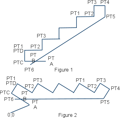
Two different LISP commands are used in the STAIR function to create points.� They are the POLAR command and the LIST command.� The POLAR command was described in Chapter 6.� Points are always represented as a list of X, Y, and maybe Z values.� The POLAR command will produce a list containing these values. The LIST command simply creates the list directly.� The statement (SETQ PTA (LIST 10 10)) sets PTA to an X value of 10 and a Y value of 10.
�
Another LISP command used by the STAIR function is REPEAT.� This command is like the WHILE command, except that there is no condition, just a number that is the number of times for the REPEAT section of the program to loop.� In our case, if there are 4 treads, the REPEAT section will loop 4 times.
�
(DEFUN C:STAIR()
��� (SETQ EXTENDIN 1)
��� (SETQ EXTENDOUT 1)
��� (SETQ TOP 4)
��� (SETQ TREADS (GETINT "Number of treads: �))
�
��� (SETQ RISE (GETREAL "Rise:<8> �))
��� (IF (= RISE NIL)(SETQ RISE 8))
�
��� (SETQ RUN (GETREAL "Run:<11> �))
��� (IF (= RUN NIL)(SETQ RUN 11))
�
��� (SETQ PTA (LIST 10 10))
��� (SETQ PTB (POLAR PTA PI EXTENDIN))
��� (SETQ PTC (POLAR PTB PI RUN))
��� (SETQ PTD (POLAR PTC (/ PI 2) RISE))
�
��� (COMMAND �LAYER� �M� �PATH� ��)
� ��(COMMAND "LINE" PTA PTC PTD� ��)
�
��� (SETQ PT1 PTD)
��� (REPEAT TREADS
������� (SETQ PT2 (LIST (+ (CAR PT1) RUN) (CADR PT1)))
������� (SETQ PT3 (LIST (CAR PT2) (+ (CADR PT2) RISE)))
������� (COMMAND "LINE" PT1 PT2 PT3 "")
������� (SETQ PT1 PT3)
��� )
�
��� (SETQ PT4 (LIST (+ (CAR PT3) TOP) (CADR PT3)))
��� (SETQ PT5 (LIST (CAR PT4) (CADR PT2)))
��� (SETQ PT6 (POLAR PT5 (ANGLE PT5 PTB) (+ (DISTANCE PT5 PTB) EXTENDOUT)))
��� (COMMAND "LINE" PT3 PT4 PT5 PT6 "")
��� (COMMAND "ZOOM" "E")
�
��� (SETQ SS (SSGET "C" (LIST (- (CAR PTB) RUN) (CADR PT6)) PT4))
��� (COMMAND "ROTATE" SS "" PTA "R" PTB PT5 PTA)
�
��� (COMMAND "LINE" (LIST 0 0) PTA "")
��� (COMMAND "CHPROP" "L" "" "C" "R" "")
��� (COMMAND "ZOOM" "E")
�
��� (PROMPT "\n********DRAWING COMPLETE********")
) ;Defun C:Stair
�
�
It is not only possible to generate G-code from a drawing, but you can also reverse the process and generate a drawing from G-code, thus showing the path that the tool will take for a particular CNC program.� The drawing that is created this way can then be inserted into the original tool path drawing to see if they match.� This is particularly useful for CNC programs that have been manually edited.
�
Depending on how elaborate you want to make your LISP function, other things besides the tool path can be tested in the CNC program.� For example, you could test to see if the X, Y, and Z values are within the physical limits of the machine.
�
SET VARIABLES AND OPEN CNC FILE
�
We will call our LISP function and file name CNCTEST.� The first two lines of the function you already know about.� The third line sets the system variable CMDECHO to 0.� When we go to draw the lines and arcs, each prompt, such as �Specify next point or [Undo]:�, will appear on the command line.� Setting CMDECHO to 0 turns that off.� The next 13 lines preset the values of different variables.� You will see what those variables are for as we go through the program.
�
The next line will ask if you want to single step through the CNC program.� If you answer �Y� the test program will stop after each move and ask you to hit ENTER to continue.� Your reply is stored as the variable SNGLSTP.� The part of the program that will stop after a move will only look for �Y�.� Anything else is considered as �N�, which is the default.� If you just hit ENTER then SNGLSTP will equal ��.� You could reply with either a �y� or a �Y�.� If you reply with �y� the next line will change it to �Y�.
�
The next thing that needs to be done is to get the file name and path of the CNC program to be tested.� That file will then be opened for reading.� The function will then look at one line at a time until it reaches the end of the file.
�
(DEFUN C:CNCTEST()
��� (SETQ OLDSNAP (GETVAR �OSMODE�))
��� (SETVAR �OSMODE� 0)
��� (SETVAR "CMDECHO" 0)
��� (SETQ COORD "ABSOLUTE")
��� (SETQ GCODE NIL)
��� (SETQ MCODE NIL)
��� (SETQ LASTX 0)
��� (SETQ LASTY 0)
��� (SETQ LASTZ 0)
��� (SETQ XVALUE 0)
��� (SETQ YVALUE 0)
��� (SETQ ZVALUE 0)
��� (SETQ MOVEFLG 0)
��� (SETQ RFLAG 0)
��� (SETQ IFLAG 0)
��� (SETQ JFLAG 0)
�
��� (SETQ SNGLSTP (GETSTRING "\nSingle Step [Y\N]
��� (IF (= SNGLSTP "y")(SETQ SNGLSTP "Y"))
�
��� (SETQ FILE (GETFILED �CNC program to test� �C:/CNCPROGRAMS/� �� 0))
��� (SETQ FP (OPEN FILE �r�))
�
��� (SETQ LN (READ-LINE FP))
���
��� ;Look at each line in CNC program file
��� (WHILE (/= LN NIL)
������� (PROMPT (STRCAT �\n� LN))
��������������� |
��������������� |
������� (SETQ LN (READ-LINE FP))
��� );While
�
��� (CLOSE FP)
) ;Defun C:Cnctest
�
READ ONE LINE AT A TIME FROM CNC FILE
�
The first line of the CNC file is read and then we go into a WHILE loop that will continue to read one line at a time.� Each time we look at a line we will look at each character in that line.� First we need to know how many characters there are and loop for that number of characters.� The LISP command STRLEN will give us the number of characters in a line of text.� We also need to keep track of where we are in the line by using a character counter.
�
��� ;Look at each line in CNC program file
��� (WHILE (/= LN NIL)
������� (PROMPT (STRCAT �\n� LN))
�
������� ;Get the number of characters in the line
������� (SETQ LINESZ (STRLEN LN))
�
������� ;Set character counter to 1
������� (SETQ CHARCNT 1)
�
������� ;Look at each character in the line
������� (WHILE (<= CHARCNT LINESZ)
��������������� |
��������������� |
������� );While
�
������� (SETQ LN (READ-LINE FP))
��� );While
�
LOOK AT EACH CHARACTER IN THE LINE
�
To get a character from the line of text we will use the LISP command SUBSTR.� The structure for this command is (SUBSTR [line of text] [start point in line] [number of characters]).� The line of text will be LN, the start point will be our character counter CHARCNT, and the number of characters will be 1.
�
We will need to do different things depending on what the character is that we are looking at, so we will branch to different functions depending on what the character is.� The LISP command that we can use to do this is COND.� The structure for this command is (COND ((condition) (command to execute))).� As you will see below, there can be any number of ((condition) (command to execute)) statements.
�
������� ;Look at each character in the line
������� (WHILE (<= CHARCNT LINESZ)
����������� ;Get the character
����������� (SETQ CHAR (SUBSTR LN CHARCNT 1))
�
����������� ;Go to the function for that character
����������� (COND ((= CHAR �G�)(GVAL))
������������������������ ((= CHAR �X�)(XVAL))
������������������������ ((= CHAR �Y�)(YVAL))
������������������������ ((= CHAR �Z�)(ZVAL))
������������������������ ((= CHAR �R�)(RVAL))
������������������������ ((= CHAR �I�)(IVAL))
����������������������� �((= CHAR �J�)(JVAL))
������������������������ ((= CHAR �M�)(MVAL))
����������� );Cond
�
����������� (SETQ CHARCNT (+ CHARCNT 1))
������� );While
�
�
GVAL FUNCTION
�
Next, we will look at the function GVAL.� No matter what function we go to, GVAL, XVAL, YVAL, and so on, we need to get the numerical value that comes after the letter.� We can use another separate function to get that value, so we will call up that function, EXTRACT, first thing in the GVAL function.
�
(DEFUN GVAL( )
��� (EXTRACT)
��������������� |
��������������� |
)
�
EXTRACT FUNCTION
�
In the EXTRACT function we need to continue looking at each character after the letter that we detected until we find the end of the value.� As long as we find numbers or a decimal point, that is part of the value.� We also need to keep track of where in the string the value starts and how many characters are in the value.� First, the character counter is advanced by 1 to step to the next character past the letter.� Then that number is saved as WORDSTART for the start point of the value.� The variable WORDCNT is used to count the number of characters and is first set to 0.� The character at the position CHARCNT is then retrieved.� Now, we need to see if that character is a number or a decimal point or something else.� The LISP command ASCII can be used to do that.� Each text character is actually stored in the computer as a number.� ASCII will give you the number for a particular character.� That number is stored as the variable ASC.� In AutoCAD, if you go to Help, Contents, Customization Guide, and ASCII Codes you will see a table of the ASCII numbers and the characters they are assigned to.
�
The text characters 0 through 9 are stored as the numbers 48 through 57.� A minus sign is 45 and a decimal point is 46.� So, we are looking at part of the value as long as the ASCII number is equal to 45 or 46 or is greater that 47 and less than 58.� That condition is used in a WHILE loop to look for the end of the value.� Each time it loops WORDCNT and CHARCNT is advanced by 1.� If CHARCNT is less than or equal to LINESZ the next character is retrieved and the variable ASC is set to the character�s ASCII number.� If CHARCNT becomes greater than LINESZ then ASC is set to 58 which will end the loop.
�
After we come out of the loop we can use the LISP command SUBSTR to extract the value.� The start point of the text will be WORDSTART and the number of characters will be WORDCNT.� The text is stored as the variable WORD.
Next, CHARCNT is decremented by 1.� When we get back to the CNCTEST function, the program needs to look at the next character after the value that was just extracted and it is possible that there is no space between the end of that value and the next character.� Moving CHARCNT back one takes care of that.
�
(DEFUN EXTRACT( )
��� (SETQ CHARCNT (+ CHARCNT 1))
��� (SETQ WORDSTART CHARCNT)
��� (SETQ WORDCNT 0)
�
��� ;Look at first character in value
��� (SETQ CHAR (SUBSTR LN CHARCNT 1))
��� (SETQ ASC (ASCII CHAR))
�
��� ;Look at rest of word
�� �(WHILE (OR(= ASC 45)(= ASC 46) (AND (> ASC 47)(< ASC 58)))
������� (SETQ WORDCNT (+ WORDCNT 1))
������� (SETQ CHARCNT (+ CHARCNT 1))
�
������� (IF (<= CHARCNT LINESZ)
����������� (PROGN
��������������� (SETQ CHAR (SUBSTR LN CHARCNT 1))
��������������� (SETQ ASC (ASCII CHAR))
����������� )
� ����������(SETQ ASC 58)
������� );If
��� );While
�
��� (SETQ WORD (SUBSTR LN WORDSTART WORDCNT))
��� (SETQ CHARCNT (- CHARCNT 1))
);Defun Extract
�
After extracting the value the program returns to the GVAL function.� The next command there changes the value from a string to an integer using the LISP command ATOI and saved as the variable GCODE.
�
We can now make some decisions about that G-code.� We can decide if the G-code represents a move or not.� If it is a move then a flag, MVFLG, is set to 1 and if it isn�t then MVFLG is set to 0.� If it is a move, we need to decide if it is a line or an arc.� If MCFLG is equal to 1 and GCODE is equal to 2 or 3 then TYPE is set to �ARC�, else it is set to �LINE�.� The variable COORD will tell us if we are in absolute mode or relative mode.� If GCODE is equal to 90, then COORD is set to �ABSOLUTE�.� If GCODE is equal to 91, COORD is set to �RELATIVE�.
�
(DEFUN GVAL( )
��� (EXTRACT)
��� (SETQ GCODE (ATOI WORD))
��� (IF (OR (= GCODE 0)
�������������� ��(= GCODE 1)
���������� ������(= GCODE 2)
������������� ���(= GCODE 3)
������������� ���(= GCODE 40)
������������� ���(= GCODE 41)
�������������� ��(= GCODE 42)
������ );Or
������ (SETQ MOVEFLG 1)
������ (SETQ MOVEFLG 0)
��� );IF
�
��� (IF (AND (= MVFLG 1) (OR (= GCODE 2)(= GCODE 3)))
������� (SETQ TYPE "ARC")
������� (SETQ TYPE "LINE")
��� )
�
��� (IF (= GCODE 90) (SETQ COORD �ABSOLUTE�))
��� (IF (= GCODE 91) (SETQ COORD �RELATIVE�))
);Defun Gval
�
XVAL, YVAL, & ZVAL
�
The next condition in the COND statement is ((= GCODE �X�)(XVAL)).� If the character �X� is found, the program goes to the XVAL function.� The first thing that the XVAL function does is go to the EXTRACT function to get the value of WORD.� The XVAL function then sets the variable XVALUE to string value of WORD changed to a decimal number by using the LISP command ATOF.� The functions YVAL and ZVAL work the same way.
�
(DEFUN XVAL( )
��� (EXTRACT)
��� (SETQ XVALUE (ATOF WORD))
)
�
(DEFUN YVAL( )
��� (EXTRACT)
��� (SETQ YVALUE (ATOF WORD))
)
�
(DEFUN ZVAL( )
��� (EXTRACT)
�� �(SETQ ZVALUE (ATOF WORD))
)
�
RVAL, IVAL, & JVAL
�
The functions RVAL, IVAL, and JVAL are a little different in that each will set a flag to show that one of these has been detected.
�
(DEFUN RVAL( )
��� (EXTRACT)
��� (SETQ RVALUE (ATOF WORD))
��� (SETQ RFLAG 1)
)
�
(DEFUN IVAL( )
��� (EXTRACT)
��� (SETQ IVALUE (ATOF WORD))
��� (SETQ IFLAG 1)
)
�
(DEFUN JVAL( )
��� (EXTRACT)
��� (SETQ JVALUE (ATOF WORD))
��� (SETQ JFLAG 1)
)
�
MVAL FUNCTION
�
The last function in the COND statement is MVAL.� In the MVAL function we will watch for an M-code of M30.
�
(DEFUN MVAL( )
��� (EXTRACT)
��� (SETQ MCODE (ATOI WORD))
�
��� (IF (= MCODE 30)
������� (PROGN
����������� (PROMPT �\n********M30 END OF PROGRAM********�)
����������� (CLOSE FP)
����������� (SETVAR �CMDECHO� 1)
������� ����(EXIT)
������� );Progn
��� );If
)
�
If MCODE equals 30, we want to prompt that M30 has been detected, close the CNC program file, set CMDECHO to 1, and exit the LISP program.� The LISP command EXIT will exit the LISP program and print �error: quit / exit abort� at the command line.
�
MV FUNCTION � DRAW THE PATH
�
After every character in one line of CNC code has been examined, the LISP program drops out of the WHILE loop that looks at each character, but we are still in the WHILE loop that looks at each line.� Before we go on to the next line we must decide what to do with the line we just looked at.� If the line indicates that a move was made we must draw a line or arc for that move.� If this line is a move then the variable MVFLAG will be equal to 1.� If MVFLAG equals 1 we will branch to another function, MV, to draw the line or arc.
�
��� ;Look at each line in CNC program file
��� (WHILE (/= LN NIL)
������� (PROMPT (STRCAT �\n� LN))
�
������� ;Get the number of characters in the line
������� (SETQ LINESZ (STRLEN LN))
�
������� ;Set character counter to 1
������� (SETQ CHARCNT 1)
�
������� ;Look at each character in the line
������� (WHILE (<= CHARCNT LINESZ)
��������������� |
��������������� |
������� );While
�
������� (IF (= MVFLAG 1)(MV))
�
������� (SETQ LN (READ-LINE FP))
��� );While
�
The first thing that is done in the function MV is to see if relative coordinates are being used.� If COORD equals �RELATIVE� then the values of XVALUE, YVALUE, and ZVALUE are changed.� The current XVALUE in this case will be a relative value.� The value of LASTX will be an absolute value.� XVALUE is added to LASTX and that gives us the new absolute value.� That absolute value replaces the current relative value of XVALUE.� The same is done with YVALUE and ZVALUE.
�
Next we check if the move is a line or arc.� If MTYPE equals �LINE� then a line is drawn from LASTX, LASTY, LASTZ to XVALUE, YVALUE, ZVALUE.
�
If the move is an arc, MVTYPE equals �ARC�, then there are some more things that we need to check.� First, we need to know if the radius method is being used, RFLAG equals 1, or if the center point method is being used, IFLAG equals 1 and JFLAG equals 1.� If RFLAG equals 1, we need to know if we are performing a G2 or a G3.� If GCODE equals 2 then we draw an arc from the current point to the last point using RVALUE.� If GCODE equals 3 then the arc is drawn from the last point to the current point.� After the arc is drawn, RFLAG is set to 0.� If IFLAG equals 1 and JFLAG equals 1 we will draw the arc using the center point.� The center point, CEN, is found by adding IVALUE to LASTX and JVALUE to LASTY.� Then, just like with the radius method, if GCODE equals 2 the arc is drawn from the current point to the last point using CEN and if GCODE equals 3 the arc is drawn form the last point to the last point to the current point.� After the arc is drawn, IFLAG and JFLAG are set to 0.
�
Now that the move has been drawn, the variable SNGLSTP that we talked about back at the beginning of the CNCTEST function comes into play.� If SNGLSTP is equal to �Y� the LISP command GETSTRING is performed with the prompt �ENTER TO CONTINYE: �.� Because we are only using GETSTRING to pause the program, we don�t need to save the string to a variable.
�
The last things that the MV function does are to save XVALUE as LASTX, YVALUE as LASTY, ZVALUE as LASTZ, and set MOVEFLG to 0.
�
�(DEFUN MV( )
��� (IF (= COORD "RELATIVE")
������� (PROGN
����������� (SETQ XVALUE (+ LASTX XVALUE))
����������� (SETQ YVALUE (+ LASTY YVALUE))
��� ����);Progn
�
��� (IF (= MVTYPE "LINE")
������� (COMMAND "LINE" (LIST LASTX LASTY LASTZ) (LIST XVALUE YVALUE ZVALUE) "")
��� )
�
��� (IF (= MVTYPE "ARC")
������� (PROGN
����������� (IF (= RFLAG 1)
��������������� (PROGN
�������� �����������(IF (= GCODE 2)
����������������������� (COMMAND "ARC" (LIST XVALUE YVALUE ZVALUE) "E" (LIST LASTX LASTY) "R"�� RVALUE)
������������������� )
������������������� (IF (= GCODE 3)
����������������������� (COMMAND "ARC" (LIST LASTX LASTY LASTZ) "E" (LIST XVALUE YVALUE) "R" RVALUE)
������������������� )
������������������� (SETQ RFLAG 0)
��������������� );Progn
����������� );If
�
����������� (IF (AND(= IFLAG 1)(= JFLAG 1))
��������������� (PROGN
������������������� (SETQ CEN (LIST (+ LASTX IVALUE) (+ LASTY JVALUE) LASTZ))
������������������� (IF (= GCODE 2)(COMMAND "ARC" "C" CEN (LIST XVALUE YVALUE ZVALUE) (LIST LASTX LASTY)))
������������������� (IF (= GCODE 3)(COMMAND "ARC" "C" CEN (LIST LASTX LASTY) (LIST XVALUE YVALUE ZVALUE)))
������������������� (SETQ IFLAG 0)
���� ���������������(SETQ JFLAG 0)
��������������� );Progn
����������� );If
������� );Progn
��� );If
�
��� (IF (= SNGLSTP �Y�) (GETSTRING "\nENTER TO CONTINUE: "))
�
��� (SETQ LASTX XVALUE)
��� (SETQ LASTY YVALUE)
��� (SETQ LASTZ ZVALUE)
��� (SETQ MOVEFLG 0)
);Defun Mv
�
After the MV function is completed we return to the CNCTEST function.� The next line in the CNC file is read and if LN does equal NIL, indicating the end of the file, we return to the top of the WHILE statement to analyze that line.
�
������� (IF (= MVFLAG 1)(MV))
�
������� (SETQ LN (READ-LINE FP))
��� );While
�
GOING FURTHER
�
What has been covered here gives you a complete �bare bones� program for drawing a tool path in AutoCAD from the CNC program file.� There is no end to the enhancements that you can add to this program, many of which would probably be for a particular brand CNC controller.� If you have more than one brand of controller, the easiest thing to do is to make a copy of this program for each controller with each copy being modified for that particular controller.� Instead of naming the files CNCTEST.LSP you might use something like ABCROUTER TEST.LSP, and XYZROUTER TEST,LSP, and so on.
�
One thing that you may want to do is to create a drawing of the router table and then always run the LISP program in that drawing.� That way you can see exactly where on the router table the path will end up.� The table in the drawing needs to be located in relation to the drawing origin the same as the physical table is in relation to the machine origin.� I suggest placing the table on its own layer and having that layer locked.
�
Another possibility is to have the program watch for a tool change and if one is detected change the drawing layer to a layer named for that tool number.� Use the MAKE option of the LAYER command to do this.
�
Those are just a few examples of what can be done using LISP and a little imagination.
�
APPENDICES
Don Jones has spent the past 20 years using and customizing AutoCAD in the stair manufacturing industry.