Machining Matching Male and Female Ellipses
There's many a slip twixt the cup and the ellipse. Here's a long and informative thread on the problem created when trying to program CNC equipment to cut two similar ellipse shapes of slightly different sizes. October 12, 2007
Question
I am attempting to make an elliptical shaped inlay in HPL about 40mm x 80mm on our Rover18. I have had good luck doing this in the past, making circles and rectangles just using the tool radius compensation to one side and then the other to do the male and female. I can't get the radius to come out right on the ellipse, but the diameters touch just fine in both directions.
Forum Responses
(CNC Forum)
From contributor S:
Is your post writing code for the ellipse as line segments instead of arcs? Can your cad system break the spline-polyline into arcs before you post the code to your CNC? This might help smooth out the output.
From contributor J:
Are you using an ellipse macro that is part of the controller? If yes, then the problem might be that the radius of the router bit is too large for such a small ellipse. You might try a smaller bit such as a 1/4" diameter. It may not make any difference, but it's worth a try.
From contributor G:
I think contributor S is on the money... If you're in AutoCAD, make sure you're not drawing real ellipses (I've also offset an ellipse, creating a spline, then flattened into a PLine), because an ellipse doesn't machine right.
From contributor M:
Ellipses are rather complex geometries to machine. One thing to understand is that simply offsetting an ellipse to try and make a smaller ellipse doesn't really make a smaller ellipse; it makes a round shaped thing that looks like an ellipse but isn't an ellipse. If you draw a 40x60 ellipse and offset that ellipse .25 to the inside, the resulting geometry would not be an ellipse, it would be that round shaped thing I mentioned earlier, but the gap between the two geometries would be .25 all the way around, which is good if that is what you want. If you draw an ellipse that is 40x60 and then draw an ellipse that is 39.5x59.5 inside the original ellipse, you may think that you would have a .25 gap between the two ellipses all the way around. This is not the case, though. You will have a .25 gap at the ends of the major and minor axes, but a varied gap between the rest of the two ellipses.
I'm not sure how your software approaches ellipses, but if it is creating separate ellipses to create the inside and outside toolpath rather than one being an offset of the other one, then you will certainly have the problem you are experiencing. If you are running AutoCAD or another CAD program, you can tinker around with ellipses by offsetting them and what not to see what I am trying to get across.
From contributor J:
"Ellipses are rather complex geometries to machine."
That depends. If the controller performs elliptical interpolation, then it's no more difficult for the user to program than a circle or an arc.
If you want your male ellipse to be slightly smaller than the female, then use the same code, change the tool comp, and very slightly decrease the tool diameter. I'm not familiar with your controller software, but it might allow you to change the tool radius from inside the program.
From the original questioner:
Thanks for the responses. I am programming at the machine only using the ellipse function, as contributor J mentioned. Don't have separate CAD program. Using a .5 inch router bit, so the 12.7mm radius should be small enough. I will try a smaller tool and see if that helps. I don't think it is an offset problem because the overall sizes are perfect.
From contributor D:
I had all kinds of machining issues with this ellipse. The machine was lurching as it made its moves on all of the ellipse arcs at the end of the petals and around the elliptical pieces that make strips. It was drawn in AutoCAD 2007, saved as a 2000 dxf, so it would import into Enroute 3.3. What do I need to do to the file to get a smooth ellipse machining? I am unclear on the previous reponses.
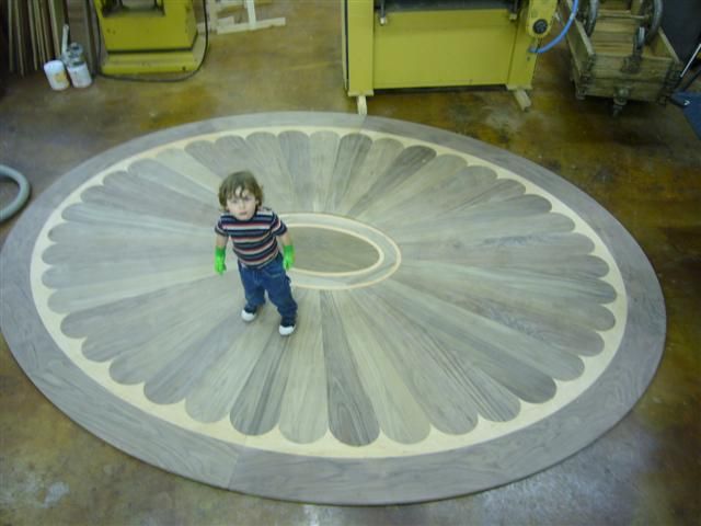
Click here for full size image
From contributor C:
Contributor M is right about the ellipse major/minor axis and the resulting curves not being equally offset by changing the axis dimensions. I would have to tinker to see if I could get the desired results just by doing an offset of some sort. No, it would not be a mathematical ellipse, but for all other practical purposes, it would suit your needs.
From contributor K:
"What do I need to do to the file to get a smooth ellipse machining?"
In AutoCAD, before you draw an ellipse, type at the command line,
pellipse
then hit enter. Set the value to 1. This will then create all ellipses in this drawing as 16 tangent polyline arcs. This will prevent your machine from lurching as it cuts the ellipse.
From contributor B:
You have all overlooked that he talks about doing this on a Rover 18. That machine is at least 10-15 years old. I am sure that this machine cannot have the same tolerances as it did when it was new. It might simply be that this machine no longer has the accuracy to do this.
From contributor E:
You could redraw your ellipse as cutter path and eliminate any cutter compensation on your machine. I've preached a few times before for programmers to understand their g code. I understand how wonderful all the new software is, but when a challenge occurs, people seem lost when their program doesn't work quite right. Look at the code and you will notice a commonality in the "lurching" areas. The lurching of your machine while it is cutting arcs is probably due to your software putting tiny little arcs at the end of each arc in the ellipse. If you are cutting using a 1/4" cutter for instance, the software may be inserting .125" R arcs in various places.
From contributor G:
Listen to contributor K above. Also, I have had success changing an ellipse to a spline, then to a polyline. Machines like polylines.
From contributor W:
I hate AutoCAD ellipses - they always give me problems. I usually use Signlab or coreldraw to draw a circle, then stretch it to the correct size to make the ellipse, then export .dxf, and the shape is always perfect and smooth. And yes, offsetting an ellipse doesn't work very well. I usually just redraw it, which only takes a minute.
From contributor J:
To the original questioner: I drew your ellipse and it appears that a 1/2" tool should work. I suggested a smaller bit only because sometimes those Biesse macros get confused when used with very small cuts. Can you further explain or illustrate "I can't get the radius to come out right on the ellipse, but the diameters touch just fine in both directions?" You are using the exact same code for both cuts, but only reversing the tool comp, correct?
From the original questioner:
That's right, using the same sizes for everything, only changing the offset direction. The problem is at the intersection of the two radiuses about .75mm gap. If you look at the shape, the two parts touch at 12 o'clock, 3, 6, and 9, but at 10, 2, 4 and 8 is the gap. I tried making the shape larger, instead of changing to a smaller tool, and the gap stayed the same. I can do the same thing with a circle and it comes out fine. The curves are smooth, by the way.
From contributor J:
That explanation helps. Code is code, so both shapes should be exactly the same because the only difference is that the tool is outside on one and inside on the other. How much bigger did you try? You might try a 36" X 24" wide ellipse and see how that aligns. I think the curves are smooth because the machine is performing elliptical interpolation, not a series of line segments.
Does your macro code look something like this?
N30 RGI=LPX/2 RGJ=LPY/2 CEI=LPX/2 CEJ=LPY/2 PAN=1 F=10 VF=3 TAG=1 DIR=0 PRF=LPZ Z=PRK PFLO=0 L=PELL
From contributor H:
Cabinetmakers have always avoided using true ellipses when fitting one shape inside another since it is not possible to draw ellipses parallel to each other. This means that the outside curve of one component cannot fit the inside curve of another, which is cut by offsetting the tool to the opposite side, since only one of them can be a true ellipse. This type of work is usually done by using the "four centered ellipse method," which is also much easier to work with. This does not produce true ellipses, but it would take a good eye to tell the difference.
From contributor I:
One other option if you use AutoCAD (I believe it started with 2004, but I might be mistaken) is to use the "FLATTEN" command. I use this on splines to convert them to polyline arcs and I would think it would work on ellipses as well, if they were drawn before pellipse was changed to 1.
From contributor K:
Contributor T is a wise man... He must be a VBA programmer.