Post-Processor Runs Amuck While Tracing Fonts
When you CNC draws crop circles while trying to cut out sign lettering, you know you've got troubles. Here, pros do some detective work and zero in on the buggy code. November 10, 2006
Question
router: Onsrud 145G12 moving gantry
control: AMC
software: AlphaCAM 6
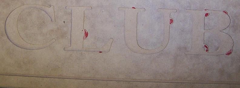
I'm trying to pocket a text logo .0625� deep consisting of a combination of Caslon fonts. Everything looks fantastic in AlphaCAM simulation, but when I run the program on the router, the bit sporadically deviates from the interior of the pocket (see the picture below), creating a number of notches along the perimeter. At one point, the bit was actually traveling completely off the spoil board, resulting in a crash and program stop.
The font in question, Adobe Caslon Bold, is somewhat more complex than Helvetica (for example), consisting of many lines and arcs. After six test runs, I finally managed to eliminate almost all of the imperfections by manually retracing the problem areas with polylines in AutoCAD, and re-importing back into AlphaCAM. Each time I had to eliminate more and more groups of tangent arcs with a straight line. This process was grossly time consuming and aggravating to say the least, and the more I modified the geometry just to get it to run, the less it appeared as the intended font.
Am I missing something here? Was the geometry created in AlphaCAM simply too complex for our post processor to handle? Is the problem originating from AlphaCAM somehow? Our router and post combo was purchased to cut much simpler, high volume shapes like slot base cabinet panels, not intricate signage. We want to broaden our capability to include jobs like this and I need to find out if our current setup is up to the task.
Click here for full size image
Forum Responses
(CNC Forum)
From contributor T:
I have an Andi with Fanuc control and AlphaCam 02 and do signage all the time. Scripts, all fonts, etc. It might be something with the control or post. Not sure there.
From contributor O:
These look like cutter comp gouges. I would suggest that you check the lead-in and lead-outs and make sure they are adequate to initiate and turn off the compensation correctly for your control.
From the original questioner:
Thanks, but there's no compensation. I'm running everything APS Tool Center.
From contributor D:
I think you are on the right path, looking at the font for the problem. There could be a loop in the vector image causing the router to cut around the loop. This loop could be invisible to the naked eye at regular magnification. Remove the loop and all will be well.
I do this kind of work on occasion, though I use Artcam insignia. It finds the loops for me, though I still have to eliminate them manually some of the time.
Have you heard of Vector Art mega collection? It is thousands of vector images and fonts that are clean and ready to import and CNC. It costs a few hundred dollars, though well worth it. I think with what you want to do, you should also take a look at Artcam, which is easy to learn and use.
From contributor F:
Use an add-in first called common line removal. Make sure all geometry is closed and proper tool direction is applied. The next thing to look at is the solid simulation. If it looks beautiful, then look at the code. I don't know what an AMC controller is, but didn't they used to make the Gremlin? Anyway, if the control reads code that a human can read, check it out. If not, submit your problem to the machine manufacturer who probably wrote the post. Pocketing 2d geometry is a simple matter for Alpha Cam. Even pocketing on angular work planes is pretty easy. I can't see why you could have a crash unless the code is bad.
From contributor Y:
What do you mean by "a combination of Caslon fonts"? Are you grouping different size letters or different font styles in the same text block? One font style could be effecting the other when post processed.
From contributor K:
I have exactly the same problem with my Biesse Rover 24 and Microvellum/ACAD. Sometimes, the errant arcs show up in the on-screen simulation, although the geometry representing the tool movement can't be seen, and sometimes, the error won't show up till the part is run on the machine. I have had some success with manually modifying the on-screen geometry and recreating code. It is a very tedious process, and only successful half of the time. I have been told that it is a known issue with ACAD, and that there isn't a fix at this time. It seems rather incomprehensible that someone hasn't come up with a workaround. I have the problem with geometry that is provided to me in DXF format, supplied by sign shops, and created with various design packages other than ACAD. This problem is severely limiting my ability to perform outsourced machining for the local sign industry, and I would very much like to have a solution.
From contributor B:
I agree with contributor D. Looks to me like you have some loops in the toolpath. Enroute always checks for open contours and loops before setting a toolpath. I can't imagine that Alphacam wouldn't, or couldn't be set up, to do the same. If you haven't already done so, zoom in on those points and see if you can see any errant line or arc segments floating around.
From contributor X:
I was having a similar problem a few years ago when we set up our Onsrud router. It has a different controller, but I tried many different things to rectify the problem and finally isolated it to the controller. There is a parameter that tells the machine when to complete an arc or circle; in my controller it is called FCT (Full Circle Threshold). Look in your post or G-code for an FCT value, and change it in the G-code to a very small number; .0001. Run the program in the air, and see if it still makes the error moves. If this solves the problem, the post can be modified to include this value in every program.
From contributor G:
This may not be your situation, but one option to check out is the following: I ran into this problem about 6-7 years ago using Bobcad and a Digitaltool router. If you have a good understanding of G code, you will easily see the error as you scroll through the code. If you are running in G91, your X and Y will read 0 as your G2 or G3 is creating an arc. In G90 you will see no change in your X and Y moves from the previous line while the G2 or G3 is creating an arc. This happens when there is a very, very small arc and your software has rounded your 3rd, 4th, or 5th place decimal to match the preceding number. This line of code can simply be eliminated since the actual movement is 0. Or you may want to try increasing the number of decimals you can output with your software. Outputting additional decimals through your software will only work if your machine will read them, however.
From the original questioner:
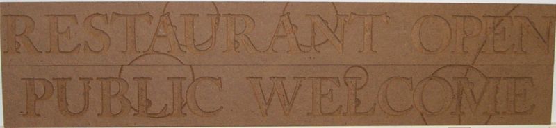
Thanks for the input, everyone. Below is another example of what I�m experiencing. These two sub signs are composed of 3/4" fire rated MDF with text pocketed in at .0625�d using a 30 degree flat tip engraving bit, and the font is Adobe Caslon Bold at 2.1875�h. The text was converted to geometry directly from the font in AlphaCAM without any touchup and the pocketing operation was a single finish pass. Behold the strange plethora of arcs and bumps so reminiscent of crop circles.
Onsrud, the router manufacturer, is focusing on the post as the culprit, stating that true type fonts need to be cleaned up prior to programming. I explained that to get the original job to run at all, I�d resorted to redrawing everything in AutoCAD by manually tracing over the AlphaCAM geometry with polyline segments, eliminating as many arcs as permitted. So now I await their revised post with fingers crossed.
Click here for full size image
From contributor W:
If you could post the .ard file, I'll take a look at it. I'm guessing the font you are using has poor geometry and that's why it is doing as it is. Depending on what version of Alphacam you are using... In the new versions they have project manager page that lets you see each element of a geometry. This makes it very easy to see what's going on with the file.
From contributor A:
This is strictly an Alphacam problem. I experienced the exact same thing 5 years ago. It has nothing to do with the control or the machine. The post needs to be modified. Good luck dealing with Alphacam; my experience was not favorable. Every two weeks I was talking to someone else.
From contributor M:
I have seen some pretty bad Alpha Cam posts that weren't written by Alpha Cam. Anyone can write a post, and many machine manufacturers write their own. This is an important distinction since your statement pointed the finger at the software. For those that don't know, the post processor is the part that outputs code for the machine. In the CAM program, geometry is drawn and toolpaths applied. After that is finished, the toolpaths are output to the post. G-code for the machine is generated by the post, not Alpha Cam itself. That is why I suspected the post processor when he said it looked great in the simulation area.
From contributor W:
I�ve been using AlphaCAM 10 plus years with these types of applications and I�m almost 99% sure that it is a geometry issue because of the type of font used. Anyone can try to write a post. Even those that make the machine and write the post don�t always get it right.
Zoom up on the corners where you see the erratic tool paths and check to see if the geometry, better yet the elements that compose the geometry, cross over each other. If this is the case, you will need to modify the geometry to get the desired tool path results you are looking for. Again, this is because of the font used and how the geometry is created from it.
From contributor B:
Personally, when I look at the .jpg of that cut, I see wide sweeping arcs seemingly inches outside of the intended cutting path. No bit should ever travel inches away from a drawn line or arc segment. If it does that, it is very likely a problem with the post or the router itself, rather than the drawing.
Yes, some fonts can be weird, but any competent CAM software should be able to work the final text as nothing more complicated than lines and arcs, applying the appropriate toolpath. This could easily be a post issue. When I open a file in Enroute, it searches out inaccuracies in the imported contours. I can't imagine a package that is as solid and widely used as Alphacam wouldn't do the same thing or something similar.
From contributor I:
I agree that this looks like a post issue. Remember, there are two basic arc interpolations:
1. using I,J coordinates or whatever else they call them specifying arc center, or
2. R (radius) variable in which case CNC calculates center of the arc.
But there are two possible centers if you output R variable from your post. Most controls have parameters specifying which side between two points is the arc. That is what I see in the pictures. If you had centers of all of your arcs that are routed wrong, moved left or down, you would still have same radius but without those bumps.
From contributor G:
Whether it's the output, post, machine is not really important. Check the G code in the area in which these crop circles are appearing. The machine, I believe, is following the code that is output. Look at the code that is creating the problem and fix it. It should take about 5 minutes. See my post above to clarify. This is a problem that stems from being too dependent on software. Learning to follow the g-code would come in handy here.
From contributor I:
True. But if this problem comes again, and again and again... I would think it makes sense to find the root cause and eliminate it. I completely agree that the programmer has to know how to code it manually. When it comes to carving and sign routing, though, I completely want to rely on CAM. That's what it is made to do. Going through hundreds or sometimes thousands of lines of code takes more time in the long run than figuring out and fixing it. Plus, there is this little feeling of satisfaction when the bulb goes on.
From contributor G:
Yes, you don't want to decode your code every time. That would be a waste of time. Going through the code this one time would truly define if the problem lies in your CAM rounding very small numbers. This is what your processor may be doing: Let's say your movement on one line of code starts as X3.22445 and is moving to X3.22446 with a 1" radius arc. This is a very small move, a move that is not seen with the naked eye. Your CAM, however, processes this to 4 decimal points, which would move from X3.2245 to X3.2245 because it rounds both numbers up. This makes your start and finish points the same. But now you are creating a 2" diameter circle rather than an extremely small arc. This gives you the crop circle. This will be fixed by having your CAM post give you an additional decimal point and your machine set to read the additional decimal. I truly believe this is your solution.
From the original questioner:
I'm sure that cranking up the precision in the post is the way to go on this one. Problem is that I haven't a clue as to how to change the settings in our post and as for looking through the code... The bible has less lines then these swoopy text programs do! If anyone knows how to do it with the default set of programs included in AlphaCAM (AlphaEDIT + RS232 Comms, I assume), then fire away because I'm all ears.
From contributor F:
Maybe he should just configure the post to output arcs defined by X,Y,I,J with X,Y being the target position and I,J being the incremental distance from the start point, with I being the X value and J being the Y value. This will eliminate the Mickey Mouse ear loops. Should be $730 with 1 being arc center and 2 being radius output. Just a thought... Editing posts can be fun, or your worst nightmare! A little knowledge is a dangerous thing.
From contributor N:
As long as AlphaCAm has a max arc radius set in the post, it will not be a post error. Occasionally short arcs with a large rad value can be misinterpreted by CNC controls. The control thinks the arc has to be achieved the long way round. Notice all errors are on arc moves, not lines. In this case, just retrace the text to make it better.
From the original questioner:
Problem solved�
$530 Output arcs as straight line segments (1 = Yes, 0 = No)
1
$531 Maximum Arc Radius - arcs will be output as straight lines if radius >
0
$532 If arcs are straight line segments, give chord error (mm or inches)
.003
Onsrud provided a revised post the week before last. It went well with one exception... without arcs, the programs are huge!
Contributor N, you're right on the money in reference to the loop-out arcs taking the long way around the circle. As for tracing... that's what I had to resort to earlier. What I think I'll do instead to counter the large file size on 'linearized' programs, is send the program out in pieces to avoid crashing the controller.
From contributor F:
I would never call that "fix" a resolved problem. Depending on the look ahead and servo parameters, running all arcs as straight line segments not only gets you huge programs, but much slower operation as cycle times.
From contributor E:
The solution, as I understand it, of eliminating all arcs and producing only line segments is absurd. This should not be considered anything more than temporary. I have run into this problem before and found it to be a combination of poor geometries and a post processor interpreting that poor geometry in the least favorable way (but usually the correct way), which is then interpreted by the control the way it was written by the post, which, in turn, is different from what the post intended. This is caused by several different geometry issues, such as very small gaps in the drawing chain, overlapping lines in the chain, and in the cases I have encountered this, as a previous post suggested, when a line exists of infinitely small length at an angle from the two lines or arcs it connects. The first two scenarios usually generate an error instead of code, but Alphacam is unfamiliar to me and it may try to cut these situations with its best guess, thereby generating the bad code, though this seems unlikely. The latter produces an arc that, as also previously suggested, starts at Xa,Ya and ends at Xa,Ya with a arc center I,J that varies depending on the geometry. Since the arc starts and stops at the same point, the control can only interpret that movement as a full circle instead of no motion at all, while the software has the precision to see it as a very small motion before rounding it up to an identical start and stop point to fit the maximum precision the control will allow. Remember that an arc motion is a motion from A to B about an arc center. G02 and G03 will always generate a motion, even if B has the same coordinates as A. This is not true of straight lines. In G00 or G01, lines (of code) moving to redundant positions are ignored.
The real question is how to fix this while retaining arc motions, which I believe are of extreme importance and should not be omitted. I am not familiar with the post processor in Alphacam or your control, so I can only generalize. Increasing the precision is unlikely to help, since most controls operate on a maximum of 3 or 4 decimal places, and these small lines can require 6-10 decimals to show up as a real motion. I prefer to clean the drawing up and have found that the mistakes the post makes disappear. This may not be the solution either, though. From the photos, it appears that the circles are not tangent to the perimeter and may originate from the middle of the pocket. If this is the case, then the problem may not lie in the original geometry, but in the resulting offset geometry created by Alphacam. Cleaning the drawing up may help Alphacam generate better tool offsets, but it may also be a bug in Alphacam. If it is possible, you may try to set a minimum length of arcs to a value like .01 mm or .005 in. Arcs of this size should be perceived by the control properly, but are small enough for practical precision. The thing to remember is that Alphacam tried to generate a tiny arc, not the big one that actually got cut. By making a minimum arc size, the tiny arc may be eliminated altogether, therefore eliminating the large arc actually cut. That is, if the post will allow such an adjustment.