By Jim Chestnut
With a background in cabinetmaking and trim work, Jim Chestnut is the inventor of the Clam Clamp, a miter clamp designed to improve the assembly and installation of door and window casings. Visit his website at miterclamp.com.
Overview
The following photo article is an attempt to share what I learned on a job that I did last winter. It was probably the most challenging cabinet job I ever did, from fabrication to installation - and was one of the most fun as well.
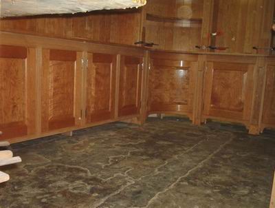
My mission was simple. "I want cherry cabinets to wrap the room from here to here, and I want the corner ones to be round. Raised panel doors on the lower ones, and the upper ones I want rounded too. Raised panel wainscotting on the other walls. I don't want any plywood and I don't want a bunch of narrow boards glued together."
The house was mid 1700's; "my" room ( 90" x 14' + or -) had floor to ceiling heights varying by 4 inches. The open end of the horse shoe forming the walls surrounding my cabinets was 3" wider than the other end.
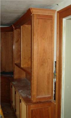
The gaps between adjacent stiles were covered with pilasters (barely seen here) after installation. Without them the installation might have continued almost indefinitely.
Except for the curved doors and the big one between them, all the door panels and wainscot panels were raised from single boards, adjacent doors from the same board. The counter is one board 18 1/2" wide. All sides and shelving (except the corner shelves) are one board. As usual, Rick of Hearne Hardwoods, came through again with some gorgeous cherry. Narrower boards were ripped for the backs. Expansion problems are discussed later in the "Installation" section.
To save on material the backs were v-matched groove and groove with splines rather than tounge and goove. The radius was cut on a Williams and Hussey rather than a shaper.
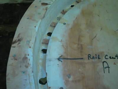
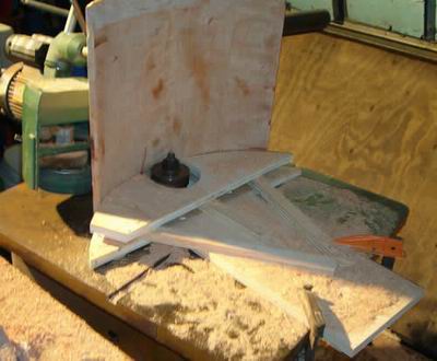
Bending form above is for not only the cabinet door rails but for the door panels and face frame rails as well. A sheet of plywood was dadoed with a router from two different radius points to form a lopsided circle. The center point (Rail center A) is one apex of the squashed circle. The formula "springback at each end = the width of the arc at its widest point (divided by) the number of plies squared" : was used to determine the pivot points for swinging the router.
This initial dado was used in conjunction with a big pattern bit to cut the rest of the plies making up the form. You may note that the dado had pads in the bottom to hold the rails off the bottom, and holes for the epoxy squeeze-out to drain. The white was pigmented shellac. The entire form was liberally paste waxed, as well all the back of the first ply and face of the last ply, prior to glueup.
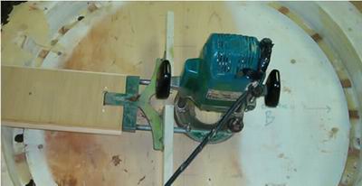
Fence look weird does it? That could be because it is installed upside down, and screwed into the plywood. It is a very quick way to make up an arch cutter. But the best thing about this arrangement is that the radius is adjustable with the wing nuts that tighten up the fence rods. So you can cut your archs slightly oversized (or undersized) then take a final light finish cut without a hassle. Plus, it can be constructed from the scrap pile - quickly.
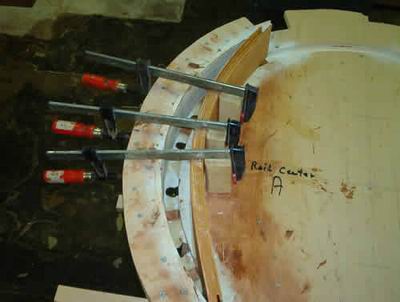
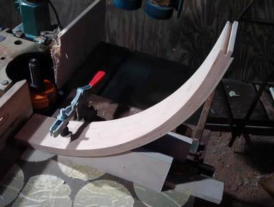
Epoxy is slipperier than sardines being trolled by a Zamboni. I was already pushing the limits by using 4 plies of cherry to make up 15/16'ths thickness, then slathering them in epoxy, waxing the backs, fronts, and the rounded edge blocks. I discovered that starting with three clamps worked best. It not only helped in keeping them from flying all over the shop, but also aided keeping them centered in the form. The relieved edges on the blocks cut down sanding time. Once the plies were into the dado, I could breathe easier. I would use 5 plies in a repeat situation though. Naturally, it's easier to work from the center out.
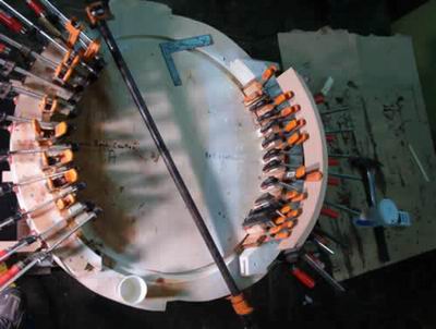
Bar clamp above was needed here to take out the slight twist that developed during glue up. You may be able to see the vertical blocks between door rail and the bessey clamps. There was just enough room between them to slide the thin square. Twisted rectangular doors can be lived with: but twisted concave radius ones are unusable. You may note that the forms extend well beyond the rails, which are longer than necessary in themselves. Incidentally, a little shellac on the forms saved a lot of paste wax. Confusing the picture is a previously glued rail sitting on top of the clamps on the right.
Only the first door rail cope angle was an eyeball gestimate, since all the rest were done without moving the plywood cradle above. The detail on this cope and stick set is a simple ovolo which is closely matched by a number of stock router bits. The stickyback sanding discs on the shaper cross slide are in pretty sad shape eh?
Before running the stiles on the shaper, I ran the radius on the face side (with knives ground to the right radius for the shaper ) to match the rails. I left the backs flat, hand planing and sanding the radius in after glue up. Plenty of extra width was available (on each stile) to adjust the shaper setup to the angle just right to meet the copes. The stile material was chosen from the closest thing I had to rift-sawed stock in my pile, to minimize movement.
It's nice to be able to climb cut the stiles on a shaper so there is no tear-out, especially when a lot of preparation went into making the stiles. Tear-out is a double no no in cases like this. Now all that's left is the sticker detail on the curved rails. This will be done with a router and a rather primitive setup, mainly because I don't know any better way to do it.. Back to Top
A bearing couldn't be used for the panel dado, though I was able to stack two tiny bearings on the 1/4 round bit (nearly identical to the slight ovolo of the shaper cutters) as a kind of fail safe for the sticker detail. Doubling up on the bearings doubles the surface area in contact with the stock so I don't get "bearing grooves" in the wood.
The fence bolted onto the router (at the top of the photo) was enormous because I had foolishly already cut two rails to length, and a smooth entry and exit from the stock was essential. This picture shows the back rail long, though coped on both ends. Since only one end of a previously detailed edge blows out on the cope, I was able to do the remaining two rails with less chance of ruining one (or more). I'll never do that again (yeah, right).
Since I wanted no tear out with the 1/4 round cutter, I climb cut, holding the router above by hand. Clamping several rails together formed a stable base for the router and fence - which was constructed from the scraps in the pile. This process had already been practiced repeatedly in beading the face frame rails.
This was, naturally, a clinched jaw operation, and I was relieved when it was finished. Murphy must have been taking a leak at the time.
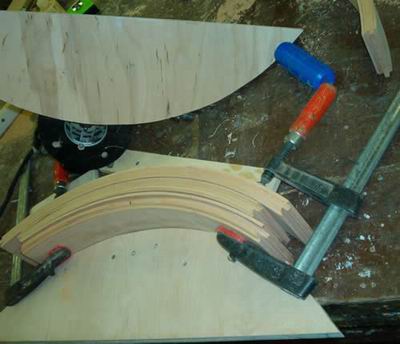
Raised Panels were glued up in the same form that glued the face frame rails and door rails. Spacing shims were required in the back on both the panel and face frame glue ups, since the door rails were thicker than either and consequently had backs with a slightly larger radius. A lot of the scrap from the original form making went to good use on this job. Yellow glue was used here rather than epoxy, for its stainless ease of use and quick set.
Assembling the face frames was also done with the aid of the glue up forms. Rails previously drilled for dowels were clamped in the forms, glued with yellow glue and stiles attached and screwed into rails from the outside edges of the stiles. An additional 2 layers of plywood was screwed and epoxied to the hidden faces of the carcass tops and bottoms to re-inforce the epoxied joint between carcass and face frame.
Though it looks like a neanderthal attempt at a crossbow, this primitive fence was worth more than the scrap it was made of. I had enough crescent moon shaped plywood and cherry laying around anyway to supply the whole third army with outhouse signs.
The cutter is in a pinch collar with a bearing rub collar. The stains on the cherry are shellac from my hands and not pieces of them. Raising the end grain was the easy part of raising the panel. Trying to get the angle just right on the sides to mate with the ends was the hard part. Basically, it was a bunch of light passes through the shaper.
I don't think it's possible to have the corners bisect on a 45, and have them the same depth, and have the flat the same thickness as the end grain, and use the same knives for both. Kind of like trying to go around a corner on a rake with one miter joint. Fortunately, I had enough extra width to experiment, and I was happy with the results.
Rough fit is complete. More details on that horror show later. Though it is not obvious from this picture, this cabinet forms a quarter circle. This means that the face frame stiles (for the moment let's consider them "door jambs) are perpendicular to each other rather than parallel like most all the other ones on earth. Also, the doors were inset into beaded face frames rather than overlaying them.
My door hanging experience, in cabinets and otherwise, might even have been a liability in dealing with these doors. Fortunately, after much whining and sniveling on my part, I had talked the customer into allowing me to use plywood for the bottom carcases.
The doors could not have been fit and hung if the backs had already been on the units. But more on this in the door hanging section.
The panels were wash coated with 1/2 lb. cut shellac then sprayed with sealer prior to glue up. Both the door and the face frame rails were constructed of the straightest grain material I had.
The Natural Way - No fuss no muss, my "Polish Naural" technique, as my buddy "Ski" calls it. It takes longer this time of year; summer is much quicker because of more UV rays - though they have to be flipped often so they don't cup. This is by far my favorite treatment for good cherry.
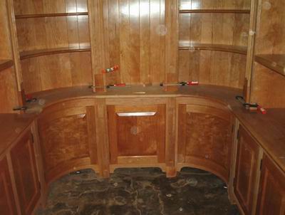
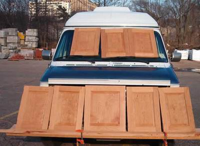
As recommended by Michael Dresdner, in his informative and hilarious book on finishing, I completely finish coated most of the parts in the shop prior to assembling and later installing on the job. The exceptions were the wide (18 1/2" x 5/4) cherry board forming the top to the lower units, the face frames and the glued up curved top shown here.
You may notice that the perimeters were coated but not the rest. This was because some jobsite fairing and sanding would be necessary on the bullnose, yet I didn't want to have to spray tight to adjacent surfaces, which would result in excess overspray. It worked quite well. Thank you Michael.
Nothing beats having your own machine shop, except maybe a ham sandwich. This dowelling jig features a choice of 5 registration marks all of which are within o.ooo5" of bearing the same relationship to each other and each drill bushing. Drills had to be sprayed with lubrication before drilling each hole, or they set the chips on fire sometimes (if they would even go through the bushings).
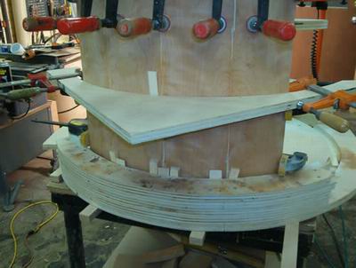
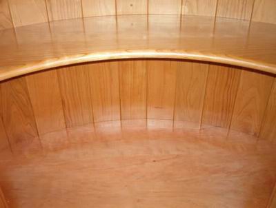
Except for the lower carcases everything had to be out of solid cherry. The tops were wide and formed a "U" shape, surrounded by walls, and had to turn 90 degrees in two places. In addition, the owner's humidifier was so powerful both Dave "dog bed" Schrader (whom I often work with) and I thought he had a plumbing leak. It was like being in the Congo Rain Forrest there. It was nice getting back to Dave's shop, where most of the fabrication was done.
So I reasoned the best way to handle expansion problems was like this. I figured that as the radius top expanded in the jungle atmosphere, its outside circumference would increase by a factor of slightly greater than pie. This should allow enough room for the back slats to expand without causing the whole thing to self destruct.
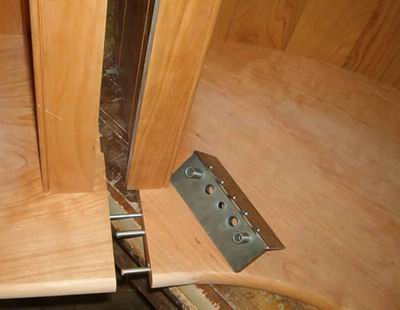
And I had bias grain meeting end grain instead of long grain meeting end grain, and burried most of the joint behind the face frames and under the sides.Only the first few inches of the tops actually touch each other. Behind the face frames, the tops have been cut back. No glue was used anywhere. Long stainless rods and dog bones were used to draw the tops together, and the stainless dowells kept them aligned. Dave and I were able, with the aid of frequent loud and plaintive stress relief expletives, to spin the corner units into the dowels sticking out of the center unit, and hook the damn thing together.
Close enough for pre-installation fairing. I had held off on assembling the sides of units adjacent to the radius corner units until I knew exactly where they should go in relation to the bullnose, and the adjacent faceframe stile. The backs, obviously didn't matter that much. All the sides were as thick as possible and had 1/2" tennons fitting into the 1/2" dados in the tops. All the straight counter tops were one board, as were all the sides and panels except the center door panel
Mating together - hummm
After wrestling with the corner units in the shop forever, I finally realized that squaring round objects was taking way too long. So I made a full scale drawing on melamine and set the corner bases on it where I gestimated they would probably go - given the shape of the room. Then I was able to size the more standard "filler" cabinets, fabricate the tops, then the uppers. But how to get them back together in the same relative position in that tiny, lopsided room was still a problem.
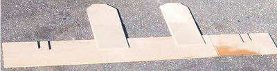
The 7 ' long gismo pictured above was just the ticket. But if I had remembered to bring it with us the first installation day, Dave and I wouldn't have gotten so adept at moving cabinets around to absolutely no purpose whatsoever for at least two hours.
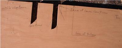
But at least it didn't rub off. Pictured here is the left side of the jig above. The outside faceframe stiles of the lower left corner unit fit into the right slot in the picture above. The oustide faceframe stile of the other corner unit fit in the corresponding slot on the other end of the jig. (In other words, one cabinet stile per each innermost slot in the first picture.)
The edges of the plywood outside the slots butted the sides of the lower cabinets. Then we brought the other corner unit stiles into contact with the two perpendicular legs (shown in the first picture) and centered the middle lower unit between them, and fastened them together.
Once we had the bottoms of the lowers all attached, we slid the jig up to the top of the lowers and repeated the proceedure. This done, we could square off the jig toward the open end of the horse shoe to determine relative "parallelity" to the walls.
The outermost slots fit into the upper units' face frames, and an addition to the perpendicular legs was hot melted on to account for the larger radius. We then repeated the same proceedure with the tops of the upper cabinets. The bottoms of the uppers could not move since they were attached to the tops.
I had never been fond of hot melt till Dave introduced me to the orange 3M guns and their large glue sticks. I won't leave the shop without it, if I can remember.
If the above process sounds easy, don't you believe it. Assembling and disassembling lowers time and again to hack and gnaw away material that can't be reached to scribe first, on a finished floor in a teeny little room in the jungle -well, never mind.
I'm just thankful I had Dave and the plywood gizmo - if only I could find a cheap maid...
Remarkably little of the sap showing on this side went through to the visable side. What little did, I touched up with that stuff Jeff Jewitt puts in the little bottles. It only takes a drop or two to ruin all your bedsheets if you sweat at night and were too exhausted to take a shower. And I used to think only Sissies wore those thin rubber gloves.
I used it very diluted after a wash coat of shellac, then sprayed. After rubbing with steel wool, I applied my top secret ageing formula - brown kiwi shoe polish. This has to be done long before the owner gets home, since it has a distinctive familiar smell, and few of us wear our Gucci's on installation jobs.
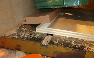
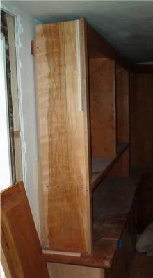
A couple core box router bit lines are visible on the side, since it wanted to cup in the shop. The end panel is leaning against the window, and you are looking at the back of it. The panel is very thick, so I hacked a taper to it with a power plane to remove stress risers.
The plywood behind the stile and against the wall are spacers for the end panel.
The End Panel bottom is shown here leaning against the top. It has been dadoed to accept the 1/2" spline on the countertop.
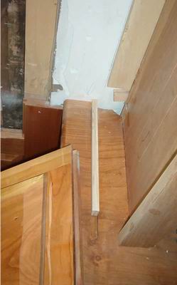
The butchered plaster around the window was indeed done by me. A previous trim guy had cased the windows with poplar, and had attached the backing for it by screwing and nailing through the rock lathe into scraps. He then cut had cut back the rock lathe along his casing line, so the lathe butted his casing. The plasterer had then skim coated to the casing.
What bummed me so bad was that I then had to mill my casing as wide as his to hide everything. And his was way too wide for that place already.
Sequence is the name in the installation game. Since I had no idea, given whatever shape that room actually was, exactly where the cabinets would start and end up, I opted to not even make the end panels until after the cabinet units and the panelling were both installed.
That way I could get the maximum panel width, and minimum stile width possible to show off the boards (matched with those on the opposing cabinet end) that I had been saving for the end panels. To further this aim I opted for flat panels coupled with an overlay molding I had copied from a piece of Victorian furniture a long time ago. I don't think the owner ever noticed that he has "reverse raised panels" on the ends.
The stile is deeply rabbeted to accept the end stile of the panelling which was screwed extremely tightly to the wall prior to the end panel being put on. After the end panel was in, those screws were removed. This left a significant hidden gap between the edge of the panelling stile and the bottom of the rabbet for movement. I've been fond of the hidden gap for many years.
Anyway? Hey Titebond CEO. Get you head out where the sun can shine. The old ones were cheaper anyway!
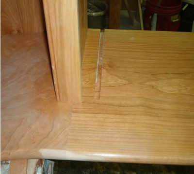
You can see that the extra thick edge of the end panel stile is flush with the front face of the adjacent face frame. (By the way, that lower end panel didn't fall out, it's just leaning there resting a bit.)
Instead of grinding most of the wood off the boards then paying to have it hauled off, I was able to get enough thickness out of selected 5/4 that the edges of the end panels doubled as backers for the pilasters. This eliminated a long glue joint with its associated sanding, eliminated a change in grain on prominent corners, and greatly facilitated minor planing chores.
Think of a regular door with "parallel" jambs. We all backplane the striker stile 3 degrees, and most of us do the same on the hinge stile to prevent hinge bind. But on concave doors such as these, which describe a quarter circle, the jambs are exactly perpendicular to each other. That means that your striker side must be 45 degrees even before you start backplaning. But that is not really much of a problem anyhow, except maybe on doors with very narrow stiles.
The problem is in fitting and hanging the door. If the top is out on a regular door, you can cheat the top hinge in and the bottom hinge out to compensate. On these doors that technique will drastically increase the vertical reveal going up the striker stile to the top rail, cause the bottom of the door to hit the bottom face frame rail somewhere near the middle and will create a big lopsided smile in the "door to face frame" reveal up top. It looks like the door rails have been re-cut with giant cookie cutters of varying accuracy every time you try an adjustment.
Imagine you are looking at a 4" plumbing coupling standing with an little clearance between two bookshelves. Now tip it slightly forward. That's what adjusting hinges does. Now make that plumbing fitting 32 inches in diameter. Fun, fun, fun.
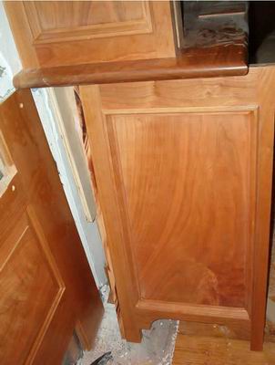
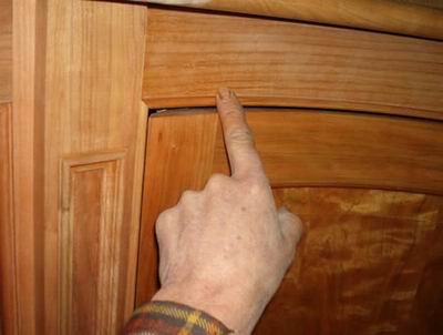
In addition is the fact that, as the door is closing, it is moving away from the face frame on the striker side. For every sixteenth that the outside edge of the door moves in to close once it clears the outside edge of the face frame, it's increasing its reveal by a bunch more than a 16th. And it looks like even more. Take another look at the picture above, and note the door's position relative to a square line drawn out from the pilaster. That door is hung and closes.
I had hung a bunch of radius interior doors a long time ago, but they were simple since they were convex. As they close, the striker reveal gets smaller. And they weren't a quarter circle either. Who would build doors on wine barrels?
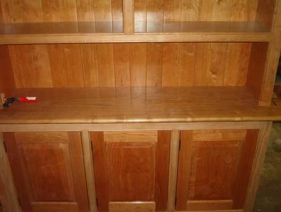
What looks like a router burn on the inside bottom of the cabinet is the shelves, which are taped to the bottom with double sided tape. Took me a while to figure that out.
Pictures even if I had a boxful, are not that useful because they are on a plane and don't show curves well. Remember the position of the door in the first picture? This one was taken from in front of the adjacent cabinet well to the left of the pilaster, which the door barely misses. So you can see how the striker reveal increases tremendously with miniscule door movement beyond the face frame.
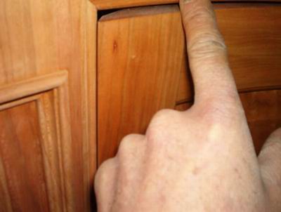
All right. I know what you're thinking, and you are wrong. A, That's shellac. And B, it's not my thumb anyway.
As you can see, I allowed just enough, possibly 1/32, clearance between the bead and the door edge. And I wound up with the same reveal that shows on the top. How much there is now, I have no idea. But he hasn't called to say he can't shut the doors.
The one good thing is that any swelling and shrinking that does occur, will have only half the effect (if even that, practically speaking) that regular doors have.
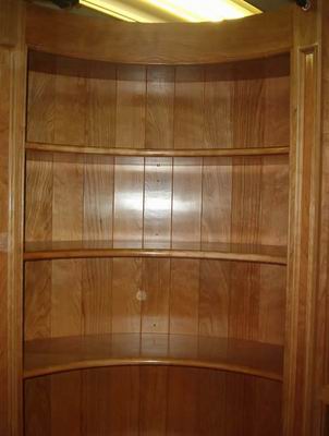
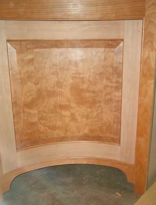
Notice how the concave surface accentuates the chatoyance of the panel. Learned that word from Michael Dresdner's book. Haven't had a chance to spout it off yet; well OK , maybe once or twice.
And I was inside there enough already. Notice that liver spot in the forground? Now that was a good party.
I finally got the doors hung with decent reveals all the way around by going very, very slowly with a hand plane. Basically, I planed and sanded until I couldn't hear it hitting the bead when closing and then stopped. I also loosened up the screws holding one of the cabinets together, tweaked it slightly, then put the back on. Fortunately, I remembered to put the shelves in before the back went on because they wouldn't fit in there afterward.
What would I do different next time. If under duress, like the certainty of slow mutilation, I would hang the face frame on the door, and then put both on the carcass. Just trying to carry those doors is a pain, and holding them out of the way to get hinge screws in the stiles was ridiculous. Much easier to move an opening, which is mainly just a hole anyway, around them.
Besides, then I could plane the carcass edges to tweak things if necessary.
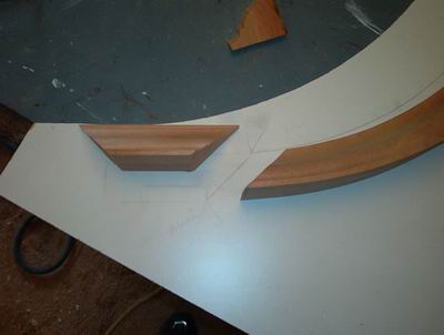
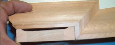
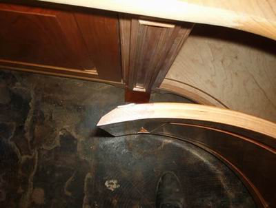
It's nice I've discovered, to save fabrication templates for further use. Here the crown radius was re-scribed and the pilasters marked in the position where they would be on the cabinets. My templates are usually the cleanest thing on the job. The crown is sitting upside down with the top on the far side.
Also note the extra length on the longer piece, and the mismatch on the joint to the right. When I leave extra, I like to leave enough so there is stock on both sides of my saw blade. I've found that saws can slide and moon cut when taking too thin a slice.
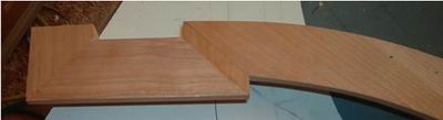
The apparant miss- mill or missed miter angle did not happen here. I had Jerry Terranova, who does all but the simplest of my radius molding work, go a little wider on the radius stock than on the straight. I've found it much better to slightly fair in a couple feet of radius, than have many feet of straight stock too heavy. The radius was on its line - the wrap backed off slightly to see the pilaster lines, and everything was parallel.
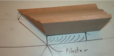
I like to back relieve nearly everything that is supposed to sit flat on something else.
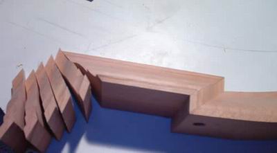
Especially when I'm gonna need a bucketful. Those returns are not for that joint. That outside corner got the return pictured below, which received a cope going into it because the adjacent piece was too long and heavy for me to handle easily alone.
These returns went to wraps like the above but were fastened to the mating long pieces on the bench. That way only outside corners (except for the coped one below) were pinned in place on the cabinets.
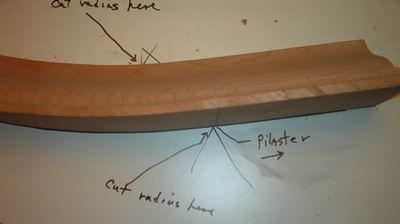
Notice the screw in that joint. The screw provided protection against my installation enthusiasm. Solid crown can have it's advantages.
In addition to being faster and easier on the body, assembling crown upside down on a flat bench ensures that nothing is rocked, and the tops remain flat and straight. It works equally well for regular crown with the addition of a perpendicular back, or fence, to the work bench. So long as the crown touches both fence and benchtop, it has to be flat and straight.
Nevertheless, I double check before setting it home if it's not too far away.
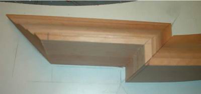
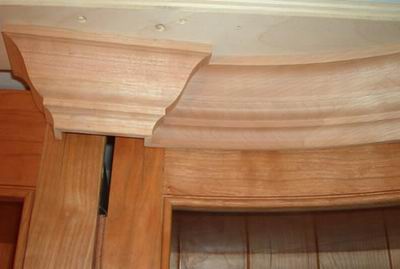
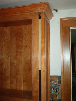
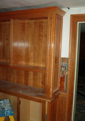
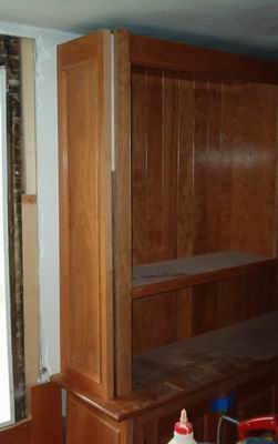
Because of the wildly fluctuating ceiling dimensions the crown was stopped short. As mentioned, the crown and face frames were coated on the job after installation. Everything that could be left off, prior to coating was; pilasters, neck molding, molding under the tops, and shelves.
All the cabinets were attached to each other with plywood spacers behind the face frames. Screws were generally used through the fronts of the face frames for the connection. This one was evidentally nailed or glued. No fasteners were used where they could be seen. Not so much for aesthetics, but because it was easier and faster and more adjustable this way. The spacers were not full width, which allowed side to side adjustment, but still prevented front to back misalignment.
Notice the farmhouse casing in the background to match the rest of the house? Before spraying casings and paneling, I added a flatener to the CV. It actually complemented the waxed 0000 wool finish on the cabs.
The last step was installing the lower plinths, pilasters, pilaster wraps and odds and ends. Upper pilaster neck molding never did go in and looks naked without it. Oh well.
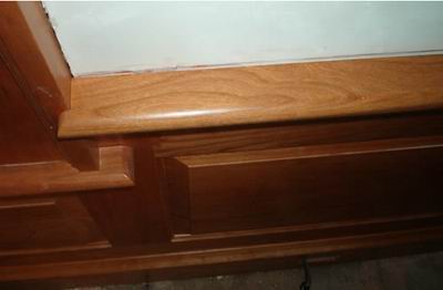
Disagreement is life and I disagree. It seems I am in a miniscule minority in using milled end grain returns for chair rails, window stools, crown caps, mantles and the like. The end of every board from a real dead tree that I have ever used has end grain on it. I don't find it's looks any more apalling than the ends of my fingers as compared to their tops. Course if the ends of my fingers have been engaged in rhinoplastic exploration that analogy doesn't apply.
Also, end grain returns do not swell up and fall off when rained on, do not need nails, do not need putty, and do not get knocked off by abuse. Indeed, end grain stool horns can be screwed from beneath up into casing legs to improve the fit. It also prevents the tradesmen climbing through the window and sitting on the stool for lunch (when you are not there to yell at them) from ruining a good fit.
This picture shows a stool horn probably 1/2" longer than customary. It was done for a reason I have long forgotten. But it could not have been done with mitered returns without looking totally ludicrous.
Besides, milled returns are faster and easier. And when something is Better, Faster, and Cheaper, I try to do it that way instead of a way that is Crummier, Slower, and More Expensive.
If you have any questions, please post them at any of the excellent forums on the web. But if you have answers, please notify me immediately at my email address, jim@miterclamp.com
With a background in cabinetmaking and trim work, Jim Chestnut is the inventor of the Clam Clamp, a miter clamp designed to improve the assembly and installation of door and window casings. Visit his website at miterclamp.com.
Editor's Note: 2Sand (website) handles a full range of sanding supplies
Forms and Bending
Fabrication
Staining and Finishing
Assembling Tops
Installing End Panels
Hanging Doors
Cutting Crown
Overview
Forms and Bending
Fabrication
Staining and Finishing
Assembling Tops
Installing End Panels
Hanging Doors
Cutting Crown