Question
When making a piece of arched trim for a door, window, etc. that is in a round room, is there a mathematical formula for determining the radius of the arch to make it fit both radii at the same time?
I've run across this a few times over the years and we always just make a pattern when it is possible, then bandsaw the trim to the lines. This correlates to a previous discussion about bandsawing plates or handrail, etc. for a radius stair. If you have the radius of the floor plate of the wall that frames the stair, when you stand it up in the air to the proper rise, it elongates the radius by what formula?
Forum Responses
(Architectural Woodworking Forum)
From contributor J:
Whenever I run into a situation that requires this, I have a Flexible Moulding made to order for any profile. I usually have a 3 week downtime for this procedure, but it sure beats the heck out of doing the math on a double radii.
The simplest application for this would be an eyebrow arch that has a fairly shallow rise. This would allow you to laminate up a curved blank that is wide enough and high enough from which to cut the moulding. For example, if your wall has a 60" radius on an outside curve, you would make up a 60" radius bending form. The next step would be to resaw approximately 1/8" to 1/4" thick material that is wide and long enough to accommodate the moulding. Then these would be laminated on the bending form. This gives you a curved board that matches the wall radius.
Next, you would simply cut the moulding out of this blank using the correct moulding radius. A simple way to accomplish that is to first cut the moulding out of bending ply and then lay that ply moulding on the bent blank. Trace and bandsaw and you're ready to go. The most complex step is profiling. This you'll have to figure out how to do based upon the equipment at your disposal.
As I said, an eyebrow moulding is the simplest application. When you get into half rounds, ellipticals and ovals, things get much more complex. Bottom line, though, is that you first have to make up some sort of curved blank that matches the wall radius, and then cut the door or window top radius out of that blank.
It is not the making of this that is my biggest problem, it is getting the pattern of what to make. We have a Mikron moulder, excellent experience at the shaper with jigs, cradles, etc.
What I am looking for is a process that gives you a radius analytically to determine the arch required. In the particular application that I have right now, one side of the opening is flat with an arched piece of trim. A header goes through the wall with that arched radius on it. The back side of this opening is in a radius wall. So the trim at the back side has a 3'-6" arch, but it is in a 9'-6" radius wall. You can't take a template that is cut to a 3'-6" radius and lay over this form or backside. It stretches over the length of this convex covering to where the pattern needs to be a larger or stretched out radius to fit. This is the correlation I am looking for.
I know, just make a template of the jamb after it is made. For more boring info than anyone cares look at George Collings book, Circular Work page 78 and 79.
So, the alternatives are to either knock the opposite side half round out of true radius as you described, or knock the jamb out of perpendicular to the two wall sides. Since the casings are high impact visual points on both walls and a minor out of square issue with the jamb would be barely noticeable, I think the solution becomes obvious.
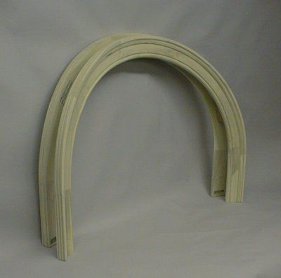
It would seem you need to increase the casing diameter to coincide with the offset at the thickest or thinnest point of the jamb (you'll have to determine which is the better choice), but keep the casing top center points lined up vertically. This will force the jamb to be out of square with the face walls, but as I said, that should not be noticeable. This is the route that was taken with the half rounds in the photo above.
As to a formula, I suspect there could be one that might help predict this relationship. However, I doubt it would be worth trying to work with one.
It sounds to me that 1/2 of your compound molding can be considered a 1/4 helix. So if you post some numbers, plan view radius, and the rise of (1/2) your molding, the spreadsheet will give the radius of what the molding is when flattened out.
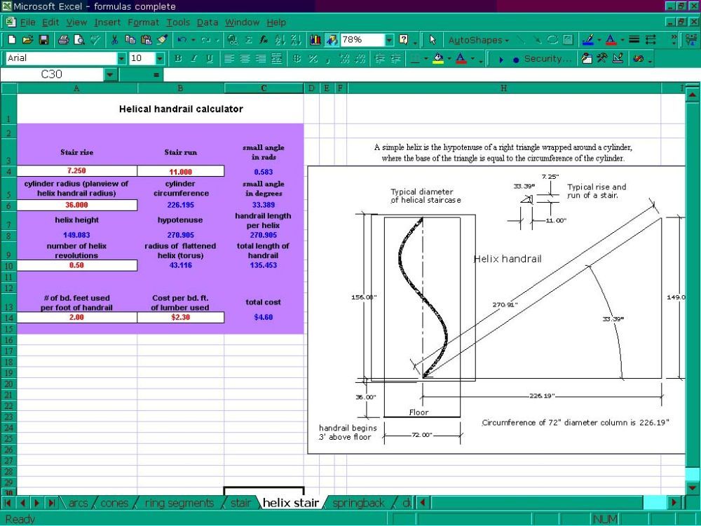
Spreadsheet Calculation Program for Curves, Angles, Compound Miters and Springback
I think that anyone reading this should play around with a mockup to completely understand what is happening with the changing dynamics of a helix. An apparent compound curve may or may not be a helical curve. The geometry of a helix has a formula. A freeform compound curve does not.
A radius molding on a curved wall may be 2 opposing partial helical curves. If so, then you would need to know the radius of the wall in plan view, and the rise and run of the helical curve in elevation view. I believe the questioner's molding is a free form curve...?