Bevel Cuts for Slope-Sided Boxes
Here's a long discussion of a tricky compound-angle problem: how to calculate the bevel cuts for a box with sides of different slopes. October 8, 2005
Question
I need some trig help. In the sketch below, my front and back tilt in at x degree and my sides tilt in at y degree. I need help figuring my bevels, marked by " ? ".
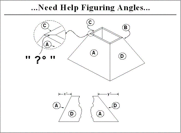
Click here for full size image
Forum Responses
(CAD Forum)
From contributor X:
Don't know if this'll help or not, but it might get you going in the right direction.
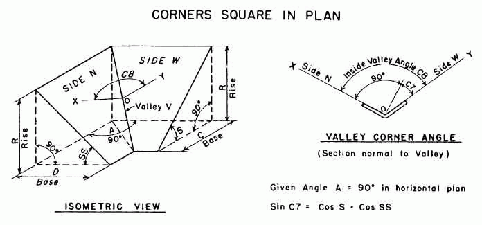
Click here for full size image
From contributor D:
You can use this formula with a scientific calculator. Once at the jobsite, I use two pieces of wood about 12" long that are nice and flat and push them into the corner and then push the slide bevel into the corner and get a snug fit. I then put the protractor on the slide bevel and split the hole at the bottom and read the degrees. I divide the number I read by 2 and use in the formula below. I also need to get the angle of the crown. This is not what most people think it is, as they use the formulas on the saws. They vary quite a bit. I stick the crown in a framer's square and mark on the square the top and bottom of the crown. I then take the slide bevel and place it on the square and adjust it so it aligns with the markings and then read the angle with the protractor. At this point I have the permanent and true angle of the crown.
M = Miter angle of saw
B = Bevel angle of saw
T-1 = Inverse tangent. Read your calculator's instructions to figure out how to get this calculation. It is frequently two key presses in a row - inverse and then tangent or function2 and then tangent.
W = Wall angle. This is what the protractor says divided by 2.
C = Crown angle. This is the angle it sits off the wall. Generally it will be between 36 and 57 degrees.
M = (TAN-1(TAN*W)(SIN*C))
B = (TAN-1(SIN*M/TAN*W)
It is actually much easier than it looks and you do not need to understand the math. You do it like this in your calculator:
1. Get your C value and write it down
2. Get your W value and write it down
3. Input the W value
4. Press TAN
5. Press the memory save button
6. Press clear
7. Input the C value
8. Press SIN
9. Press X (times)
10. Press the memory recall button
11. Press =
12. Press the inverse button
13. Press the TAN
14. This is your miter angle. Write it down rounded to 1/10th of a degree (if it was 38.34567, you would write down 38.3).
15. Press clear
16. Input the W value
17. Press TAN
18. Press the memory save button
19. Press clear
20. Input the M value you just wrote down
21. Press SIN
22. Press / (divide)
23. Press the memory recall button
24. Press =
25. Press the inverse button
26. Press the TAN
27. This is your miter angle. Write it down rounded to 1/10th of a degree (if it was 18.74587, you would write down 18.7).
You now have your miter and bevel angles for your saw. This works just fine for vaulted ceilings and the whole process is very fast. It is not nearly as time-consuming as it appears here. With paint grade crown, you can measure your angle to Ĺ degree and for stain grade, you should work to ľ degree and they will be exact and tight.
If your saw is not perfect, you may have to introduce a fudge factor. Typically it is something to do with the bevel angle. If it does not come out perfect, adjust your bevel angle in 1/4" degree increments until it is correct. Once you get it, letís say your saw bevel is off 1 full degree, then just add or subtract that 1 degree all the time when you set the saw.
From contributor A:
This is another way to skin a cat.
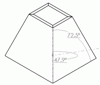
This is the same model in a different configuration. Parametrics are good for this sort of thing. Aren't we talking about different slopes? But for a practical solution I do it the same way as contributor D - just put the 2 pieces on a framing square and use a protractor. Really, modeling is doing the same thing in the computer - just creating points in space.
From contributor E:
Contributor X, thank you. I have wanted to be able to calculate that miter for years. I come across this for making kitchen sloped hood enclosures. I have had to trial and error miter the mating parts in CAD and try to see if there is a fit. The guys in the shop then use the miter angle I give them as a starting point for their own trial and error fitting. Hopefully no more of that. Now I can figure the angle exactly, quickly. I fiddled with it to put it into the context of a hood enclosure and it works! (At least the virtual parts mated perfectly in CAD.)
The formula uses the angle of the sloped front and sloped sides entered as degrees off vertical. Bevel is the amount to tilt the saw from vertical. Here is the formula:
Bevel=90-(90+arcsin((cos(90-side slope))(cos(90-front slope))))/2
From contributor X:
I've had guys from the shop ask me this 2 or 3 times in a 6 year span, and I have had to tell 'em, "I'm not sure - I could draw it up in 3d and give you the specific angle, but it'd be a while... I'm right in the middle of something else." By the time I was free, they had already got it by trial and error themselves.
What I'd like is a cut and dried formula. Simple trig... just plug in the values, and bingo. Done.
"Bevel=90-(90+arcsin((cos(90-side slope))(cos(90-front slope))))/2"
Smells like a lisp to me :)
To the original questioner: you should test this out for your various conditions and let us all know how it flies. Then we could all put it in our arsenal. It seems to me this is only valid for case; orthogonal in plan section. It'd need to be adapted if your box were other than 4 sided.
From contributor E:
"Smells like a lisp to me"
What does that mean?
The sketch you posted - did it come from a book?
From contributor P:
Go to this link and download the spreadsheet.
http://www.woodweb.com/knowledge_base/_Spreadsheet_Calculation_Program.html
I wrote this a few years back. In the workbook, go to the dualslope worksheet. Enter your 2 slopes in the white cells with red fonts. Do not change the wall angle.
I've been meaning to get the spreadsheet updated, cause I've since locked the worksheets and added a few more problem solving worksheets. Still have not solved the partial cone formula yet.
From contributor E:
Contributor P, thanks for posting that great spreadsheet. There are things there I can put to use. Naturally, I went to the dual slope sheet to compare with the formula I posted based on contributor X's diagram/formula. It was interesting to find the bevel values returned differ slightly. When entering both of the slopes at 0, 90 or 45 degrees, both formulas return the same value for bevel. Other slope entries I fiddled with, 30 and 15, 45 and 15 returned slightly different values for bevel. Next time I have to make a sloped hood I'll do some MDF mockups and see which formulas yield a better fit in the shop. The other two fields in your spreadsheet, side miter and end miter, are going to be useful too. I used these values shaping my two virtual 3-D test pieces and it seems to be right on. For me, this was another trial and error affair just like the bevel value.
From contributor X:
What I meant was this formula could easily be written into a lisp program where side-slope and front-slope could be entered in at the (autocad) command line and the program spits back your miter angle.
Martindalecenter.com is quite a site, with answers to all your quantum physics questions.
From contributor E:
Here is an example of the variance: 30 degree side slope, 15 degree end slope. The Martindale's sketch formula returns 41.282 degrees. Contributor P's spreadsheet returns 40.789 degrees.
From contributor P:
There is certainly confusion here for the readers of this thread. A crown molding-compound miter formula does not solve the questioner's box that has a different slope on the ends than the front and back. He was not asking for a crown molding calculation. In the spreadsheet that I wrote, I have 2 different worksheets that solve: 1- crown molding calculation (you can also do the miter cuts for a sloped polygon planter) and 2- compound miter calculation for a 4 sided pedestal, with 2 different slopes.
Over the years I have read that making a 3-d drawing will give you angles you need to cut. But I have never seen anyone submit a drawing with dimensioned angles that give you compound miter information. Will someone please do this, and keep track of your time drawing so everyone can see how it is done? And possibly make your dwg or dxf drawing available for download at WOODWEB here so we all can play around with the example.
From contributor A:
Thanks for the spreadsheet! Is this enough information to prove out the math? I can't export a 3d dxf. There is e-viewer (solidworks). I have never used it.
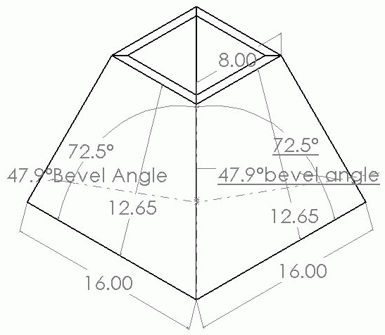
Click here for full size image
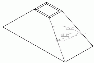
Here is the other one. In Sw I just created an assembly and lofted the sides. I then created a plane that is perpendicular to the face and the edge that would be run on the saw and dimensioned the angle. This is one model with different configurations. I took about 20 minutes to create the assembly and maybe 5 minutes to create the new configuration. Infinite Configurations can be created and saved, and in some situations this is very useful. Like the tapered tables I mentioned earlier. I haven't gone to the saw and checked this. I guess I should.
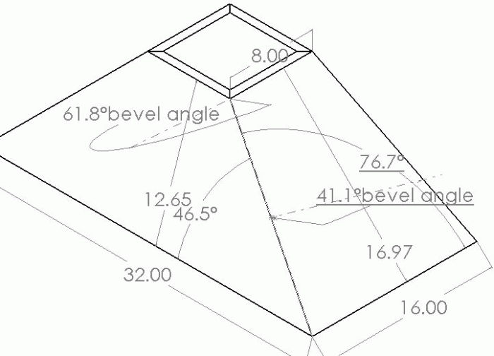
Click here for full size image
From contributor A:
Whoops - the bevel angle is actually 51.5, 102.9/2.
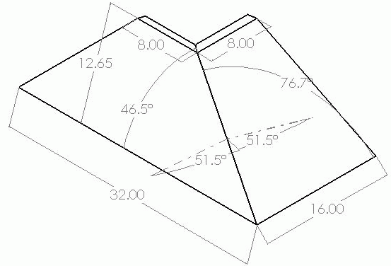
Click here for full size image
From contributor P:
I was going to put numbers to the example above. A box that slopes 46.5 on 2 sides, and 76.7 on the other 2 sides. The angles to enter into the worksheet cells are the complimentary angles of the above numbers, since my formula works from a vertical line angle, (top to bottom on the box center), not the horizontal line angle as seen in the drawing posted. 43.5 (90-46.5) and 13.3 (90-76.7). The results are bevel of 38.46 and side miter of 9.73 and the other miter is 42.72. I'll try and get the mockup cut tomorrow, and see if the numbers are correct.
From contributor A:
Contributor P, those numbers are the angle cut. These are the numbers for the slope. 45deg on the long side and 18.43 on short side.
I did check my numbers today on the saw and they appear to be correct. But it wouldn't be the first time I was wrong.
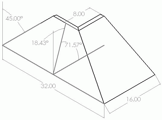
Click here for full size image
From contributor E:
Contributor A's example, 45 end slope and 18.43 side slope:
Contributor P's spreadsheet returns 36.98 bevel.
The Martindale formula returns 38.54 bevel.
Contributor A's says 51.5 bevel. Are we talking about the same thing? (90-51.5=38.5, that sounds right.) Bevel being the amount to tilt the saw from 90.
From contributor D:
Contributor P is correct about the confusion. Sorry about that, my bad. Here is something I threw together in ACAD in under 5 minutes. That was for the modeling, and not the 2D drawing of the 3D model. I had to think about what to do to get the actual angles of the table saw and display them in a way a shop person would understand.
It is assuming the pieces are not molding, but larger panels that will be cut on a table saw. If someone wants to confirm the numbers, that would be great.
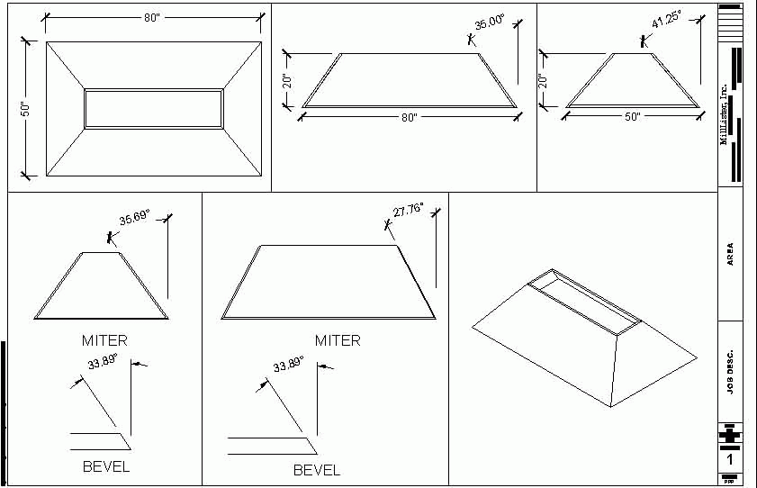
Click here for full size image
From contributor E:
Contributor D, I get the same bevel (33.89) for your example of 35 and 41.25 slopes using the formula I posted earlier. Contributor P's spreadsheet returns the same numbers for miter angle.
The comments below were added after this Forum discussion was archived as a Knowledge Base article (add your comment).
Comment from contributor C:
It's surprising how something like this that is so simple can be made so complex. The angle desired here can be done on a drafting table or with 2-D CAD. 3-D CAD (solid modeling) is not required. The concept of auxiliary views taught in a basic drafting class is all that is necessary. The trick is to create the view that shows the joint in true length and then develop an auxiliary view perpendicular to that line. Since the joint will then be a point, the angle between the adjacent sides will be true.


